http://up-ship.com/blog
Feb 112010
As a followup to THIS and THIS,
here’s an example of what might be in the actual book… the section on
the Cole/Helios internal nuclear pulse propulsion system (if you want to
see more on Cole/Helios, check out issue Volume 1, Number 3 of Aerospace Projects Review. Also much better-rez images, and more of ‘em).
<> The final book would likely have several different illustrations (as well as larger ones), largely for copyright reasons. A book of this type would necessarily have to be graphics-heavy, and getting licensing for a whole bunch of art would probably be cost prohibitive (for example, a major arospace company who’s name begins with “B” and ends with “ing” typically wants about $400 per illustration… *far* beyond my, or pretty much anybodies, means). In Word format, the following fills up 11 pages. Multiply that by the outline previously published, and you’ll get a hint as to the scope and size of the book.
………………..
The Helios Concept
The notion of using atomic weapons as part of a powerful spacecraft propulsion system arose shortly after the dust had settled from the first atomic blast in New Mexico during the summer of 1945 With an energy denisty vastly greater than any conceivable chemical propellant, the idea of using the blast from an atomic bomb to push a spacecraft was simply too attractive to pass up.
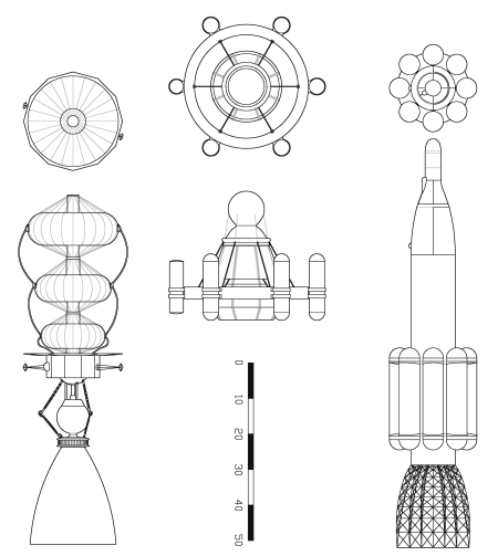
While studies of the Orion concept were underway, work was underway elsewhere on a related but quite different propulsion system. From 1959 to 1961, Dandridge Cole, a visionary engineer at the Martin Company in Denver, Colorado, produced theoretical studies of vehicles propelled by contained nuclear explosions. In this concept, the atomic device would be detonated within a large spherical chamber; a nozzle would direct the blast in an orderly stream directly aft. The clear advantage of this system was that a vast proportion of the bomb’s energy could be harnessed, whereas the Orion concepts used only ten percent or so of the bomb’s energy.
Coles studies focused on four very theoretical concepts; no real engineering design work seems to have been done.
Cole’s “Model I” vehicle was dominated by a 130 foot diameter steel sphere. With a wall thickness of 0.5 inches, the sphere alone weighed 1,000,000 pounds. The payload, shock absorbers and propellant were contained within a structure mounted forward of the steel sphere. The Model I was intended for use as a space vehicle not a launch vehicle, although it was considered possible for the Model I to boost itself into Earth orbit. A standard mission was to leave Earth orbit and soft-land on the moon, drop its payload, return to Earth and aerobrake into orbit. Payload was to be 350,000 pounds. Alternate missions would have taken the Model I from Earth orbit to Mars or Venus; mission velocities of 26,000 ft/sec were possible.
The atomic bomb “energy capsules” had a yield of 0.01 kilotons, or the equivalent of 10 tons of explosive power. A total of 2,400 of these energy capsules would be carried. In order to provide useful thrust, 858 pounds of water would be pumped into the chamber just before each detonation. This would be done through transpiration cooling channels in the wall of the sphere. By using the power of the energy capsules to heat water, the Model I gained two important features: firstly, the water helped cool the sphere, and secondly, the water served as a reaction mass for the bomb’s energy to work with. Had a propellant not been used, the bomb would have served as an effective means of heating the chamber, but would have done little towards accelerating the vehicle. A total of 2,060,000 pounds of water was carried onboard.
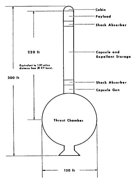
Cole’s Model 1 (Martin, 1961)
The wall thickness of the Model I steel sphere was dictated by the potential use of the vehicle within Earths atmosphere. At sea level, 85,000 pounds of air would be contained within the vessel; the walls would be subjected to a sudden overpressure of 310 psi. For purely space missions, where the sphere would not see operation within an atmosphere, the wall thickness, and thus weight, could be reduced substantially.
Cole preferred using a Nova class chemical rocket booster to loft the Model I to orbit, but considered self-launch. By increasing the pulse rate, thrust would be increased to where the thrust to weight ratio was adequate for boost. Cole also mentioned that since the total energy release during boost would be less than that released by a single multi-megaton bomb, then atmospheric contamination by radioactive particles would be correspondingly less. What Cole didn’t mention, however, was that in order to get a nuclear device to detonate with only 0.01 kilotons yield, it must be made intentionally inefficient, and hence rather filthy.
Engine performance for the Model I was not spectacular, and was in fact considerably lower than for the baseline Orion vehicle. Thrust was 800,000 pounds, with a specific impulse of 931 seconds. Thrust-to-weight for a Model I operating at one pulse per second was 0.25, which was adequate for lunar landing missions. Orion performance was expected to be far superior. NERVA-style nuclear thermal engines would be capable of similar performance, with far less fallout.
Cole’s Model II was a straightforward evolution of the Model I. The thrust chamber weight was reduced to 200,000 pounds by using stronger materials, and specific impulse was increased to 1,150 seconds by replacing the water propellant with hydrogen. The number of energy capsules would be increased to 5,800; these were expected to cost $10,000 each. The mass of hydrogen expelled with each pulse was 558 pounds. Payload would be increased to 2,920,000 pounds. Vehicle gross weight was 6,720,000 pounds.
The Model IIa was also sketched out. This was a simple tenfold mass scaleup of the Model II. This included scaling up the thrust chamber to 282 feet diameter, and increasing energy capsule yield to 0.1 kilotons. The main advantage of this scaleup was derived from the fact that the energy capsules would not cost substantially more to have an increased yield. This would also result in a slightly increased specific impulse of 1,350 seconds.
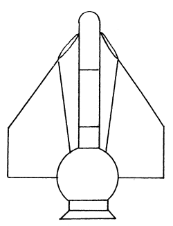
The fourth, and most entertaining, of Coles designs was the Nuclear Pulse Jet. This was, in essence, a pulsejet similar to that used on the V-1 “Buzz Bomb” of World War II , scaled up and using atomic bombs instead of chemical fuel. This vehicle would be used specifically for Earth surface to orbit operations.
Sketch of Nuclear Pulse Jet (Martin)
No design details were provided for this vehicle, apart from the basic concept. By raising pulse rate to two per second and using atmospheric air for propellant, average thrust of the Nuclear Pulse Jet was to be 9,660,000 pounds. Coles comments on atmospheric contamination are a clear anachronism, pointing out that the late 1950s-early 1960s was a different era, when people were more willing to take risks for potentially great rewards. “It may be decided that the relatively minor health hazard from this contamination is far less a matter for concern than, say, the exhaust from 50 million automobiles, and should be accepted philosophically as one of the penalties we pay for civilization and progress.” Cole also proposed the use of “clean” bombs, something still not available (at least so far as is known). Very low-yield bombs have been built, but they use much the same mass of very expensive fissile material as much higher-yield bombs. Very low yields are achieved by making the fission reaction inefficient and incomplete… unfortunate side effects include a great deal of very radioactive fallout and considerable variability in yield.
Little interest was shown by the USAF, NASA or Martin higher management, and Cole’s vehicle concept faded away. It appears that no true engineering studies or detailed vehicle design efforts were undertaken, although a considerable amount of art was created of the concept.
While Cole and Martin did no further work of note on the internal detonation concept, the idea received further study at Lawrence Livermore Laboratory in California. Starting late in 1963, this program ran under the name Project Helios. While this program also did not apparently produce engineering studies of vehicle configurations, it did produce more detailed studies of pulse unit and thrust chamber requirements. The thrust chamber design was given highest priority. Also, artwork of conceptual Helios vehicles was produced. While no engineering data has been produced to back these paintings up, they are of a much higher technical order than those produced at Martin and appear fairly realistic given the propulsion system.
The initial Helios study concept called for a vehicle of 1,500,000 pounds in Earth orbit, intended for a manned mission to Mars. Payload delivered to mars orbit (the Helios vehicle itself would not go to the Martian surface) was on the order of 50 tons; total mission velocity to be achieved was 60,000 ft/sec. The vehicle would be assembled in Earth orbit from components launched by conventional boosters.
For the first vehicle iteration (Jan 1964) the optimum number of pulses would be about 4000; each would have a yield of only 4 tons (0.004 kilotons). Each charge would mass about 100 pounds. Five hundred pounds of hydrogen would be introduced into the 20 to 50 foot diameter thrust chamber; a small amount of carbon would be added to increase radiation absorption. The chamber was initially expected to mass about 80 tons. Thrust would be two or three million pounds (nine or thirteen million Newtons) for 0.1 seconds; pulses would occur every ten seconds… averaging out to two to three hundred thousand pounds of thrust.. By January of 1965, the chamber was 30 feet in diameter; the pulse unit yield was 5.1 tons (0.0051 kt), and the hydrogen propellant was reduced to 150 pounds per pulse.
Considerable effort was put into calculation of thrust chamber wall conditions and structural design. Wall temperatures would peak at about 14,000 K slightly less than two milliseconds after detonation, with a pressure maximum of 5.25 kilobars at the same instant. These were instantaneous values, and rapidly dropped to manageable levels. Calculations suggested that 4.5% or more of the energy of each pulse would be retained in the chamber walls as heat after propellant discharge. This was about the same as the allowable maximum heat retention, which implied that further analysis would have to be done. Several potential chamber wall materials were tested. One that showed considerable promise was a laminate of 0.062 inch thick titanium alloy (Ti – 5 Al – 2.5 Sn) sheets, bonded with a silver alloy. It was found that a six-ply laminate had 80% of the toughness of a single same-thickness sheet of the same alloy, while it had 6 times the fracture toughness of bar stock of the same alloy.
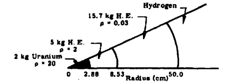
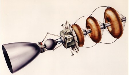
The pulse units assumed for the vehicle were quite simple in overall design. A rather simple sphere only one meter in diameter, most of the unit was a low density high explosive shell. In the core was a 2 kg uranium sphere; it was jacketed by a higher density shell of high explosive. This combination would produce an explosive yield equivalent to 5.1 tons of TNT.
Pulse unit (Not To Scale)
While the amount of uranium expended with each pulse was rather small, during the course of a baseline mission several tons would be used. Also, while the pulse units were able to use a small quantity of uranium to produce the desired effect, it was an inefficient system… ten times that amount of uranium would have produced more than one thousand times the energy release. So, in effect, while the Helios concept would have generated a high specific impulse and made efficient use of the energy available, the way in which it used valuable fissionable material was very inefficient. Only a small fraction of the uranium would properly fission; the rest would be vaporized, leaving a trail of radioactive waste behind the Helios vehicle.
Also standing in the way of the Helios concept were the throat conditions experienced by the large thrust chamber. Throat temperatures of 4000 Kelvin were expected, well beyond the ability of known materials to handle. Also, the radiative heating on the walls of the chamber would also have been very high, stressing the wall material nearly to the maximum allowable tolerance. These heating problems, in conjunction with the high engine mass of internal detonation systems, compared poorly to external detonation systems. Also, despite Dandridge Cole’s models, the internal detonation systems do not scale up well.
As a result of these difficulties, and the Nuclear Test Ban Treaty, work on Helios was halted 1965. No similar concepts have since come to light.
The engine should be a fairly simple affair… a spherical detonation chamber married to a nozzle. The size of the nozzle and the throat would depend on the role of the engine… is it strictly an in-space propulsion system, or is it intended to operate within an atmosphere? If the latter, the nozzle will be shorter, with a lower expansion ratio than an equivalent in-space system. Despite the unconventional nature of the energy source, the basic performance of the Helios engine is fundamentally like that of a conventional liquid rocket engine, and can be calculated using the same processes described in section XXX. This type of engine scales down rather poorly, limited by the ability to create a reliable, consistent and fully self contained pulse unit… a sub-kiloton nuclear device of consistent yield is difficult to manufacture. Unless a “nuclear hand grenade” is developed (which is of course conceivable in a science fiction world), anything much smaller than what was described for Helios is unlikely.
For an air breathing Cole engine, inlets would obviously be required. The flow path to the engine should be as straight and unobstructed as possible. Flow straighteners may be used to make sure that the airflow into the engine is as consistent as possible. The exact mechanisms for injecting air into the engine can vary substantially… a vast multitude of small injectors spread around the periphery of the spherical chamber is likely the best approach, but a smaller number of larger, simpler injectors may also be used if a secondary engine coolant system is employed. A combination of a few discrete air injectors coupled with a vast number of liquid injectors would probably work well.
In operation, a Helios-style engine would pulse once or less per second. Unlike Orion, Helios not only needs to fire a nuclear pulse unit, but also a large quantity of reaction mass; engineering difficulties with this would limit pulse rate. Compared to Orion, the need for complex shock absorbers would be reduced. While Orion involved a mechanical impulse against the pusher plate that would last only microseconds, Cole/Helios engines would spread the impulse out over around one tenth of a second. In this case, it would probably be easier and more cost efficient to put the payload on shock absorbers.
Since the propulsion system operates by pulses separated by noticable periods of time, from large fractiong of a second to several seconds, structural flexing could quite likely be noticable.
External bracing is quite likely and appropriate, depending upon the vehicle. For a vehicle intended for atmospheric flight, especially an atmospheric “cruiser,” any such structural reinforcement would most likely be encase in an aerodynamic shroud.
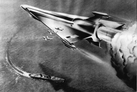
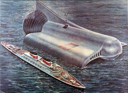
Martin Company artwork showing Nuclear Pulse Jet in operation. The vehicle seems to be designed as a seaplane. For scale reference, note the flight of Martin P6M SeaMaster bombers that are about to get vaporized, and the shadow of the spaceplane on the water. The ship below appears to be the S.S. United States, which had a length of 990 feet. This image is not to be taken as a faithful representation of contemporary Martin design efforts, but as pure marketing.
Coles “Aldebaran,” as painted by space artist Roy Scarfo. In 1959, Dandridge Cole envisioned craft such as this being the backbone of the space launch industry in the 1980-1990 timeframe. The Aldebaran was to be able to carry 60,000,000 pounds of payload into low Earth orbit, or soft-land 45,000,000 pounds on the Moon. Scale is shown by comparing the Aldebaran to the liner SS. United States; the helicopter shown loading cargo into the Aldebaran also helps show the substantial size envisioned. Clearly, if the vehicle could carry 60 million pounds of payload, it would need a bigger payload loading door than the one shown. Curiously, a secondary cockpit or observation deck is shown on the vertical fin.
Coles “Macrolife” concept spacecraft, painted in 1960. By using contemporary rocket vehicle growth curves, Cole expected vessels of this size to be built by the end of the twentieth century. Carrying 10,000 or more colonists, the “Macro-Life” vehicles would be fully self-contained and self-sufficient, needing only to stop off at the occasional asteroid or comet for raw materials. Note that the nozzle appears to be very short, and that the throat appears to be quite large, a good fraction of the diameter of the chamber.
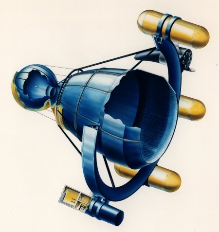
This Lawrence Livermore “Helios” concept seems to show, at first glance, a ground launch vehicle. However, the exposed truss-structure around the engine bell argues against that; what was probably the goal here was to put the crew compartment and payload as far from the detonation chamber as possible. This design also puts the pulse units between the crew and detonations, providing further radiation protection. Also visible are support rods on the pulse units, which were, presumably, to assure that the unit was properly positioned within the chamber for detonation. This sort of setup would assure that the pulse rate would be low.
This was clearly a design for a Mars vehicle. At the extreme front of the Helios is a landing craft that looks much like a model rocket; tucked in behind that is a winged Earth return vehicle of a type studied for several other Mars vehicles. The tanks strapped to the side of the vehicle are for liquid hydrogen propellant storage. (courtesy Livermore Labs)
This shows what is clearly a design meant for on-orbit assembly. The three toroids appear to be inflatable structures, most likely habitation volume for the crew. This vehicle may have been meant to spin to provide artificial gravity.
Volume for pulse units and propellant seems to be very limited. Again, though, it appears to be a Mars vehicle, owing to the winged lander (which appears to have legs for a tail-landing). What the jointed arms are for is something of a mystery… engine gimbal seems unlikely, and they would make poor shock absorbers. (courtesy Livermore Labs)
A very unusual configuration. What was hoped to be gained by this layout is unclear; being clearly an on-orbit assembled design, length is fairly unimportant, and this puts the crew quite close to the detonations and radioactive exhaust. Note the “afterburner.” Exactly how this was meant to work is unclear. (courtesy Livermore Labs)
Helios reconstructions based on the preceding artists impressions. (copyright 2007, Scott Lowther)
NOTE: this section would describe known examples of the concept as used in prior books, Movies, TV series, etc. Commentary and criticism on the designs and usage would be provided.
Martin/Cole Studies:
Cole, D. “The Feasibility of propelling Vehicles by Contained Nuclear Explosions,” Advances In the Astronautical Sciences, Vol. 6, pp. 726-742, 1961.
Yaffee, M. “Martin Proposes Nuclear Rocket Plan,” Aviation Week, January 25, 1960, pp. 34-35.
Cole, D. Beyond Tomorrow – The Next Fifty years In Space, Amherst Press, Amherst Wisconsin, 1965.
Helios Studies:
Helios Quarterly Report No. 1, January 27, 1964, , University of California, Lawrence Radiation Laboratory, Livermore, California
Helios Quarterly Report No. 2, June 4, 1964, , University of California, Lawrence Radiation Laboratory, Livermore, California
Helios Progress Report No. 3, January 6, 1965, University of California, Lawrence Radiation Laboratory, Livermore, California
Helios artwork courtesy Laboratory Archives, University of California, Lawrence Livermore National Laboratory
<> The final book would likely have several different illustrations (as well as larger ones), largely for copyright reasons. A book of this type would necessarily have to be graphics-heavy, and getting licensing for a whole bunch of art would probably be cost prohibitive (for example, a major arospace company who’s name begins with “B” and ends with “ing” typically wants about $400 per illustration… *far* beyond my, or pretty much anybodies, means). In Word format, the following fills up 11 pages. Multiply that by the outline previously published, and you’ll get a hint as to the scope and size of the book.
………………..
The Helios Concept
The notion of using atomic weapons as part of a powerful spacecraft propulsion system arose shortly after the dust had settled from the first atomic blast in New Mexico during the summer of 1945 With an energy denisty vastly greater than any conceivable chemical propellant, the idea of using the blast from an atomic bomb to push a spacecraft was simply too attractive to pass up.
While studies of the Orion concept were underway, work was underway elsewhere on a related but quite different propulsion system. From 1959 to 1961, Dandridge Cole, a visionary engineer at the Martin Company in Denver, Colorado, produced theoretical studies of vehicles propelled by contained nuclear explosions. In this concept, the atomic device would be detonated within a large spherical chamber; a nozzle would direct the blast in an orderly stream directly aft. The clear advantage of this system was that a vast proportion of the bomb’s energy could be harnessed, whereas the Orion concepts used only ten percent or so of the bomb’s energy.
Coles studies focused on four very theoretical concepts; no real engineering design work seems to have been done.
Cole’s “Model I” vehicle was dominated by a 130 foot diameter steel sphere. With a wall thickness of 0.5 inches, the sphere alone weighed 1,000,000 pounds. The payload, shock absorbers and propellant were contained within a structure mounted forward of the steel sphere. The Model I was intended for use as a space vehicle not a launch vehicle, although it was considered possible for the Model I to boost itself into Earth orbit. A standard mission was to leave Earth orbit and soft-land on the moon, drop its payload, return to Earth and aerobrake into orbit. Payload was to be 350,000 pounds. Alternate missions would have taken the Model I from Earth orbit to Mars or Venus; mission velocities of 26,000 ft/sec were possible.
The atomic bomb “energy capsules” had a yield of 0.01 kilotons, or the equivalent of 10 tons of explosive power. A total of 2,400 of these energy capsules would be carried. In order to provide useful thrust, 858 pounds of water would be pumped into the chamber just before each detonation. This would be done through transpiration cooling channels in the wall of the sphere. By using the power of the energy capsules to heat water, the Model I gained two important features: firstly, the water helped cool the sphere, and secondly, the water served as a reaction mass for the bomb’s energy to work with. Had a propellant not been used, the bomb would have served as an effective means of heating the chamber, but would have done little towards accelerating the vehicle. A total of 2,060,000 pounds of water was carried onboard.
Cole’s Model 1 (Martin, 1961)
The wall thickness of the Model I steel sphere was dictated by the potential use of the vehicle within Earths atmosphere. At sea level, 85,000 pounds of air would be contained within the vessel; the walls would be subjected to a sudden overpressure of 310 psi. For purely space missions, where the sphere would not see operation within an atmosphere, the wall thickness, and thus weight, could be reduced substantially.
Cole preferred using a Nova class chemical rocket booster to loft the Model I to orbit, but considered self-launch. By increasing the pulse rate, thrust would be increased to where the thrust to weight ratio was adequate for boost. Cole also mentioned that since the total energy release during boost would be less than that released by a single multi-megaton bomb, then atmospheric contamination by radioactive particles would be correspondingly less. What Cole didn’t mention, however, was that in order to get a nuclear device to detonate with only 0.01 kilotons yield, it must be made intentionally inefficient, and hence rather filthy.
Engine performance for the Model I was not spectacular, and was in fact considerably lower than for the baseline Orion vehicle. Thrust was 800,000 pounds, with a specific impulse of 931 seconds. Thrust-to-weight for a Model I operating at one pulse per second was 0.25, which was adequate for lunar landing missions. Orion performance was expected to be far superior. NERVA-style nuclear thermal engines would be capable of similar performance, with far less fallout.
Cole’s Model II was a straightforward evolution of the Model I. The thrust chamber weight was reduced to 200,000 pounds by using stronger materials, and specific impulse was increased to 1,150 seconds by replacing the water propellant with hydrogen. The number of energy capsules would be increased to 5,800; these were expected to cost $10,000 each. The mass of hydrogen expelled with each pulse was 558 pounds. Payload would be increased to 2,920,000 pounds. Vehicle gross weight was 6,720,000 pounds.
The Model IIa was also sketched out. This was a simple tenfold mass scaleup of the Model II. This included scaling up the thrust chamber to 282 feet diameter, and increasing energy capsule yield to 0.1 kilotons. The main advantage of this scaleup was derived from the fact that the energy capsules would not cost substantially more to have an increased yield. This would also result in a slightly increased specific impulse of 1,350 seconds.
The fourth, and most entertaining, of Coles designs was the Nuclear Pulse Jet. This was, in essence, a pulsejet similar to that used on the V-1 “Buzz Bomb” of World War II , scaled up and using atomic bombs instead of chemical fuel. This vehicle would be used specifically for Earth surface to orbit operations.
Sketch of Nuclear Pulse Jet (Martin)
No design details were provided for this vehicle, apart from the basic concept. By raising pulse rate to two per second and using atmospheric air for propellant, average thrust of the Nuclear Pulse Jet was to be 9,660,000 pounds. Coles comments on atmospheric contamination are a clear anachronism, pointing out that the late 1950s-early 1960s was a different era, when people were more willing to take risks for potentially great rewards. “It may be decided that the relatively minor health hazard from this contamination is far less a matter for concern than, say, the exhaust from 50 million automobiles, and should be accepted philosophically as one of the penalties we pay for civilization and progress.” Cole also proposed the use of “clean” bombs, something still not available (at least so far as is known). Very low-yield bombs have been built, but they use much the same mass of very expensive fissile material as much higher-yield bombs. Very low yields are achieved by making the fission reaction inefficient and incomplete… unfortunate side effects include a great deal of very radioactive fallout and considerable variability in yield.
Little interest was shown by the USAF, NASA or Martin higher management, and Cole’s vehicle concept faded away. It appears that no true engineering studies or detailed vehicle design efforts were undertaken, although a considerable amount of art was created of the concept.
While Cole and Martin did no further work of note on the internal detonation concept, the idea received further study at Lawrence Livermore Laboratory in California. Starting late in 1963, this program ran under the name Project Helios. While this program also did not apparently produce engineering studies of vehicle configurations, it did produce more detailed studies of pulse unit and thrust chamber requirements. The thrust chamber design was given highest priority. Also, artwork of conceptual Helios vehicles was produced. While no engineering data has been produced to back these paintings up, they are of a much higher technical order than those produced at Martin and appear fairly realistic given the propulsion system.
The initial Helios study concept called for a vehicle of 1,500,000 pounds in Earth orbit, intended for a manned mission to Mars. Payload delivered to mars orbit (the Helios vehicle itself would not go to the Martian surface) was on the order of 50 tons; total mission velocity to be achieved was 60,000 ft/sec. The vehicle would be assembled in Earth orbit from components launched by conventional boosters.
For the first vehicle iteration (Jan 1964) the optimum number of pulses would be about 4000; each would have a yield of only 4 tons (0.004 kilotons). Each charge would mass about 100 pounds. Five hundred pounds of hydrogen would be introduced into the 20 to 50 foot diameter thrust chamber; a small amount of carbon would be added to increase radiation absorption. The chamber was initially expected to mass about 80 tons. Thrust would be two or three million pounds (nine or thirteen million Newtons) for 0.1 seconds; pulses would occur every ten seconds… averaging out to two to three hundred thousand pounds of thrust.. By January of 1965, the chamber was 30 feet in diameter; the pulse unit yield was 5.1 tons (0.0051 kt), and the hydrogen propellant was reduced to 150 pounds per pulse.
Considerable effort was put into calculation of thrust chamber wall conditions and structural design. Wall temperatures would peak at about 14,000 K slightly less than two milliseconds after detonation, with a pressure maximum of 5.25 kilobars at the same instant. These were instantaneous values, and rapidly dropped to manageable levels. Calculations suggested that 4.5% or more of the energy of each pulse would be retained in the chamber walls as heat after propellant discharge. This was about the same as the allowable maximum heat retention, which implied that further analysis would have to be done. Several potential chamber wall materials were tested. One that showed considerable promise was a laminate of 0.062 inch thick titanium alloy (Ti – 5 Al – 2.5 Sn) sheets, bonded with a silver alloy. It was found that a six-ply laminate had 80% of the toughness of a single same-thickness sheet of the same alloy, while it had 6 times the fracture toughness of bar stock of the same alloy.
The pulse units assumed for the vehicle were quite simple in overall design. A rather simple sphere only one meter in diameter, most of the unit was a low density high explosive shell. In the core was a 2 kg uranium sphere; it was jacketed by a higher density shell of high explosive. This combination would produce an explosive yield equivalent to 5.1 tons of TNT.
Pulse unit (Not To Scale)
While the amount of uranium expended with each pulse was rather small, during the course of a baseline mission several tons would be used. Also, while the pulse units were able to use a small quantity of uranium to produce the desired effect, it was an inefficient system… ten times that amount of uranium would have produced more than one thousand times the energy release. So, in effect, while the Helios concept would have generated a high specific impulse and made efficient use of the energy available, the way in which it used valuable fissionable material was very inefficient. Only a small fraction of the uranium would properly fission; the rest would be vaporized, leaving a trail of radioactive waste behind the Helios vehicle.
Also standing in the way of the Helios concept were the throat conditions experienced by the large thrust chamber. Throat temperatures of 4000 Kelvin were expected, well beyond the ability of known materials to handle. Also, the radiative heating on the walls of the chamber would also have been very high, stressing the wall material nearly to the maximum allowable tolerance. These heating problems, in conjunction with the high engine mass of internal detonation systems, compared poorly to external detonation systems. Also, despite Dandridge Cole’s models, the internal detonation systems do not scale up well.
As a result of these difficulties, and the Nuclear Test Ban Treaty, work on Helios was halted 1965. No similar concepts have since come to light.
Uses:A “Cole/Helios” style nuclear pulse engine could be used for both ground launched designs as well as pure in-space systems. With the ability to use atmospheric air as reaction mass, the Cole-type engine could be used for atmospheric cruise as well as launch.
The engine should be a fairly simple affair… a spherical detonation chamber married to a nozzle. The size of the nozzle and the throat would depend on the role of the engine… is it strictly an in-space propulsion system, or is it intended to operate within an atmosphere? If the latter, the nozzle will be shorter, with a lower expansion ratio than an equivalent in-space system. Despite the unconventional nature of the energy source, the basic performance of the Helios engine is fundamentally like that of a conventional liquid rocket engine, and can be calculated using the same processes described in section XXX. This type of engine scales down rather poorly, limited by the ability to create a reliable, consistent and fully self contained pulse unit… a sub-kiloton nuclear device of consistent yield is difficult to manufacture. Unless a “nuclear hand grenade” is developed (which is of course conceivable in a science fiction world), anything much smaller than what was described for Helios is unlikely.
For an air breathing Cole engine, inlets would obviously be required. The flow path to the engine should be as straight and unobstructed as possible. Flow straighteners may be used to make sure that the airflow into the engine is as consistent as possible. The exact mechanisms for injecting air into the engine can vary substantially… a vast multitude of small injectors spread around the periphery of the spherical chamber is likely the best approach, but a smaller number of larger, simpler injectors may also be used if a secondary engine coolant system is employed. A combination of a few discrete air injectors coupled with a vast number of liquid injectors would probably work well.
In operation, a Helios-style engine would pulse once or less per second. Unlike Orion, Helios not only needs to fire a nuclear pulse unit, but also a large quantity of reaction mass; engineering difficulties with this would limit pulse rate. Compared to Orion, the need for complex shock absorbers would be reduced. While Orion involved a mechanical impulse against the pusher plate that would last only microseconds, Cole/Helios engines would spread the impulse out over around one tenth of a second. In this case, it would probably be easier and more cost efficient to put the payload on shock absorbers.
Appearance:With each pulse there would be a momentary blinding flash from dead center of the detonation chamber. The reaction mass would flare to incandescence and flood out of the engine as a conventional exhaust. With water as the reaction mass, the exhaust would be largely indistinguishable from a conventional hydrogen/oxygen rocket engine, with the exception that the exhaust plume would last for only a small fraction of a second (no more than about 0.1 seconds). The throat was expected to get extremely hot, and would thus glow white hot for several seconds at least. Cooling would best be done by evaporating a fluid through the throat, which would produce a super heated but largely non-propulsive vapor between pulses.
Since the propulsion system operates by pulses separated by noticable periods of time, from large fractiong of a second to several seconds, structural flexing could quite likely be noticable.
External bracing is quite likely and appropriate, depending upon the vehicle. For a vehicle intended for atmospheric flight, especially an atmospheric “cruiser,” any such structural reinforcement would most likely be encase in an aerodynamic shroud.
Examples (Real World):
Martin Company artwork showing Nuclear Pulse Jet in operation. The vehicle seems to be designed as a seaplane. For scale reference, note the flight of Martin P6M SeaMaster bombers that are about to get vaporized, and the shadow of the spaceplane on the water. The ship below appears to be the S.S. United States, which had a length of 990 feet. This image is not to be taken as a faithful representation of contemporary Martin design efforts, but as pure marketing.
Coles “Aldebaran,” as painted by space artist Roy Scarfo. In 1959, Dandridge Cole envisioned craft such as this being the backbone of the space launch industry in the 1980-1990 timeframe. The Aldebaran was to be able to carry 60,000,000 pounds of payload into low Earth orbit, or soft-land 45,000,000 pounds on the Moon. Scale is shown by comparing the Aldebaran to the liner SS. United States; the helicopter shown loading cargo into the Aldebaran also helps show the substantial size envisioned. Clearly, if the vehicle could carry 60 million pounds of payload, it would need a bigger payload loading door than the one shown. Curiously, a secondary cockpit or observation deck is shown on the vertical fin.
Coles “Macrolife” concept spacecraft, painted in 1960. By using contemporary rocket vehicle growth curves, Cole expected vessels of this size to be built by the end of the twentieth century. Carrying 10,000 or more colonists, the “Macro-Life” vehicles would be fully self-contained and self-sufficient, needing only to stop off at the occasional asteroid or comet for raw materials. Note that the nozzle appears to be very short, and that the throat appears to be quite large, a good fraction of the diameter of the chamber.
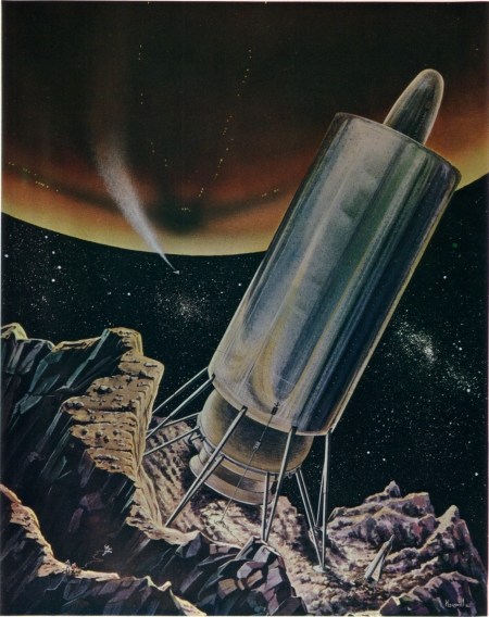
This Lawrence Livermore “Helios” concept seems to show, at first glance, a ground launch vehicle. However, the exposed truss-structure around the engine bell argues against that; what was probably the goal here was to put the crew compartment and payload as far from the detonation chamber as possible. This design also puts the pulse units between the crew and detonations, providing further radiation protection. Also visible are support rods on the pulse units, which were, presumably, to assure that the unit was properly positioned within the chamber for detonation. This sort of setup would assure that the pulse rate would be low.
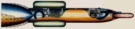
This was clearly a design for a Mars vehicle. At the extreme front of the Helios is a landing craft that looks much like a model rocket; tucked in behind that is a winged Earth return vehicle of a type studied for several other Mars vehicles. The tanks strapped to the side of the vehicle are for liquid hydrogen propellant storage. (courtesy Livermore Labs)
This shows what is clearly a design meant for on-orbit assembly. The three toroids appear to be inflatable structures, most likely habitation volume for the crew. This vehicle may have been meant to spin to provide artificial gravity.
Volume for pulse units and propellant seems to be very limited. Again, though, it appears to be a Mars vehicle, owing to the winged lander (which appears to have legs for a tail-landing). What the jointed arms are for is something of a mystery… engine gimbal seems unlikely, and they would make poor shock absorbers. (courtesy Livermore Labs)
A very unusual configuration. What was hoped to be gained by this layout is unclear; being clearly an on-orbit assembled design, length is fairly unimportant, and this puts the crew quite close to the detonations and radioactive exhaust. Note the “afterburner.” Exactly how this was meant to work is unclear. (courtesy Livermore Labs)
Helios reconstructions based on the preceding artists impressions. (copyright 2007, Scott Lowther)
Examples (fictional):N/A
NOTE: this section would describe known examples of the concept as used in prior books, Movies, TV series, etc. Commentary and criticism on the designs and usage would be provided.
Background References:Martin, A. and Bond, A. “Nuclear Pulse Propulsion: A Historical Review of an Advanced Propulsion Concept,” Journal of the British Interplanetary Society, Vol. 32, pp. 283-310, 1979
Martin/Cole Studies:
Cole, D. “The Feasibility of propelling Vehicles by Contained Nuclear Explosions,” Advances In the Astronautical Sciences, Vol. 6, pp. 726-742, 1961.
Yaffee, M. “Martin Proposes Nuclear Rocket Plan,” Aviation Week, January 25, 1960, pp. 34-35.
Cole, D. Beyond Tomorrow – The Next Fifty years In Space, Amherst Press, Amherst Wisconsin, 1965.
Helios Studies:
Helios Quarterly Report No. 1, January 27, 1964, , University of California, Lawrence Radiation Laboratory, Livermore, California
Helios Quarterly Report No. 2, June 4, 1964, , University of California, Lawrence Radiation Laboratory, Livermore, California
Helios Progress Report No. 3, January 6, 1965, University of California, Lawrence Radiation Laboratory, Livermore, California
Helios artwork courtesy Laboratory Archives, University of California, Lawrence Livermore National Laboratory
No comments:
Post a Comment