Friday, November 28, 2014
Dynomak fusion details and summary of other nuclear fusion projects
November 27, 2014
There has been some recent coverage of the Dynomak nuclear fusion project in IEEE Spectrum and other sources over the last few days.Nextbigfuture had extensive coverage of the Dynomak over 6 weeks ago. Dynomak makes the claim that they will be cheaper than coal power. The Dynomak is priced out at about $2.7 billion for a 1 gigawatt nuclear reactor. Nuclear fission reactors in China are lower than that cost and China's coal plants tend to be cheaper. China is developing a follow on to pressure water reactors which is the super-critical water reactors. The supercritical water reactor might be commercially ready around 2025 and could be about $1.5 to 2 billion for a 1 gigawatt nuclear reactor. The Canadian Terrestrial Energy molten salt reactor could have its first commercial scale unit in 2020 and could eventually be less than 1 cent per kilowatt hour.
Nextbigfuture had an updated summary of the prospects for commercial nuclear fusion. Below is a new update.
The Dynomak reactor system is the possible realization of economical fusion enabled by Imposed-Dynamo Current Drive (IDCD). IDCD could enable a spheromak commercial fusion development path.
• High CD (Current drive) efficiency improves over the tokamak.
• 30% CD efficiency enables the spheromak with high TBR and economically competitive with coal.
The HIT-SI, a cold (~10-20 eV) concept exploration experiment, has demonstrated such efficient sustainment with adequate confinement. (Reaches stability beta-limit with current drive power) IDCD.
The Steady Injective Helicity Injection method has achieved 90 kA toroidal current and current gains approaching 4.
NIMROD simulations of a bigger and hotter HIT show fluctuations may not break flux surfaces of stable equilibria
.png)
The Dynomak Reactor System Highlights
* Energy efficient IDCD for sustainment of a high beta spheromak configuration
* Immersive, molten-salt blanket system for first wall cooling, tritium breeding, and neutron moderation
* YBCO high-temperature superconductors for PF coil set
* SC-CO2 (supercritical carbon dioxide) secondary cycle (reviewed favorably by Westinghouse)
.png)
.png)
An economical fusion development path is proposed to reach Dynomak scale device
• Promising results from HIT-SI and NIMROD and an economical conceptual reactor design justifies Proof-of-Principle (PoP) experiment.
• PoP seeks to demonstrate adequate confinement at high temperature with IDCD on an inexpensive, pulsed machine.
• With successful PoP, the development path includes steady-state operation and nuclear engineering.
.png)
The Dynomak device is a spheromak with the aspect ratio of a spherical tokamak and shaped like a reversed field pinch. It is driven with only IDCD. The six inductive handle-shaped drivers use low-cost AC ( 40 kHz) power. Resistively heated to a few keV, the experiment has a 3.2 MA, 5 second pulse with a 2.5 s plasma current ramping duration. Its minor radius is 1.0 meter with aspect ratio 1.5. There is no toroidal field coil or anything linking the torus yet it has an engineering beta-limit as high as 16%. As a design-class project its reactor potential was assessed to be competitive with conventional power sources, undercutting coal and on par with natural gas with carbon capture. Costing using several ITER-developed components gave $1.2B.
Conclusions
• HIT-SI results indicate sustained spheromaks with pressure.
• Computer simulations indicate closed flux with large magnetic fluctuations.
• An IDCD driven spheromak enables economical fusion power [The Dynomak]
• Encouraging spheromak and RFP results and economical conceptual reactor justifies Proof-of-Principle experiment.
• IDCD driven spheromak development path may provide a cost effective approach to fusion energy.
$32 million Proof of Principle
.png)
.png)
.png)
Here is 2014 presentation
.png)
Reference
There have been several Spheromak experiments.
The spheromak is a Magnetic Fusion Energy (MFE) configuration, which is a leading alternative to the tokamak. It has a simple geometry which offers an opportunity to achieve the promise of fusion energy if the physics of confinement, current drive, and pressure holding capability extrapolate favorably to a reactor
Commercialization Targets for Nuclear Fusion Projects
LPP Fusion (Lawrenceville Plasma Physics) - the target is to make LPP Fusion with a commercial system 4 years after net energy gain is proved. The hop is two years to prove net energy gain. Then 2019-2022 for a commercial reactor (2022 if we allow for 3 years of slippage). They could lower energy costs by ten times.
Lockheed Compact Fusion has a target date of 2024 and made big news recently with some technical details and an effort to get partners.

Helion Energy 2023 (about 5 cents per kwh and able to burn nuclear fission waste)
Tri-Alpha Energy (previously talked about 2015-2020, but now likely 2020-2025)

General Fusion 2023 (targeting 4 cents per kwh)
EMC2 Fusion (Released some proven physics results, raising $30 million)


Dynomak Fusion claims that they will be able generate energy cheaper than coal. They are not targeting commercialization until about 2040.
MagLIF is another fusion project with good funding but without a specific target date for commercialization.
There is Muon Fusion research in Japan and at Star Scientific in Australia.
There is the well funded National Ignition facility with large laser fusion and there is the International Tokomak project (ITER).
General Fusion in Vancouver has its funding with Jeff Bezos and the Canadian Government. (As of 2013, General Fusion had received $45 million in venture capital and $10 million in government funding)
EMC2 Fusion results from October 2014
IEC Fusion (EMC2 fusion) had several million in Navy funding but is now seeking about $30 million in funding.
For years, EMC2 Fusion Development Corp. has had to conduct its research into what's known as Polywell fusion outside public view because the Navy wanted it that way. Now the Navy is phasing out its funding, and EMC2 Fusion is planning a three-year, $30 million commercial research program to see if its unorthodox approach can provide a fast track to cheap nuclear fusion power.
EMC2 Fusion's latest findings on its Polwell approach are more positive than skeptics suspected but not as positive as some supporters hoped.
"This finding ... is just one step along the way," said M. Simon, a frequent contributor to the Talk-Polywell online discussion forum. "It makes the case that further experiments are warranted. In other words, no showstoppers."
Nicholas Krall, a plasma physicist who has been working in the fusion field for more than a half-century and has been an adviser to EMC2 Fusion, was more enthusiastic. "I think this is the most exciting experimental advance that I've been involved in," he told NBC News. 'I'm stoked."
.png)
Arxiv - High Energy Electron Confinement in a Magnetic Cusp Configuration [EMC2 Fusion publication]
EMC2 reports experimental results validating the concept that plasma confinement is enhanced in a magnetic cusp configuration when beta (plasma pressure/magnetic field pressure) is order of unity. This enhancement is required for a fusion power reactor based on cusp confinement to be feasible. The magnetic cusp configuration possesses a critical advantage: the plasma is stable to large scale perturbations. However, early work indicated that plasma loss rates in a reactor based on a cusp configuration were too large for net power production. Grad and others theorized that at high beta a sharp boundary would form between the plasma and the magnetic field, leading to substantially smaller loss rates. The current experiment validates this theoretical conjecture for the first time and represents critical progress toward the Polywell fusion concept which combines a high beta cusp configuration with an electrostatic fusion for a compact, economical, power-producing nuclear fusion reactor.
.png)
The high-pressure confinement, also known as high-beta confinement, is what's described in the ArXiv paper. One of the keys to solving that problem was to redesign the Wiffle-Ball to do away with the joints between the reactor's rings, Park said.
However, the test device did not demonstrate the neutron production that would be required for an actual fusion reaction. "We tried to do it, but we just didn't have enough equipment to do it," Park said. "We thought that getting the Wiffle-Ball effect validated was a good accomplishment."
Park is proud of the fact that his team proved the Wiffle-Ball design could work — confirming a theoretical claim that was first made 56 years ago by physicist Harold Grad. But EMC2 Fusion still has to show that the design can support a fusion reaction that eventually produces more power than is put into the system. Such a system would have to smash ions together in the center of a hot, magnetized cloud of electrons.
For the Navy-supported project, EMC2 Fusion concentrated on the prospects for an exotic kind of hydrogen-boron fusion known as pB11. But if the project goes commercial, the company would consider more mainstream options such as deuterium-tritium.
Park said he's already been having discussions with potential backers for the next experimental phase.
"It'll be great if we get funding," he said. "But even if we don't, I think there will be somebody who will be excited if they understand what all this means. There could be a bit of a race, too. If the race happens, I'm playing to win the race."
Krall is anxious to see that race heat up. He acknowledged that EMC2 Fusion hasn't yet determined whether or not a working Polywell fusion reactor is feasible — but at the age of 82, he's counting on Park to get the answer to that question soon.
"He thinks we can reach break-even in seven years, and we can get to proof of principle in four years. Seven years, I can wait that long," Krall told NBC News. "I've had a good career, but I'll be a lot happier if I can see a break-even fusion device before I kick off."
Tri-alpha energy has good funding.
As of 2014, Tri Alpha Energy is said to have hired more than 150 employees and raised over $140 million, way more than any other private fusion power research company. Main financement came from Goldman Sachs and venture capitals such as Microsoft co-founder Paul Allen's Vulcan Inc., Rockefeller's Venrock, Richard Kramlich's New Enterprise Associates, and from various people like former NASA software engineer Dale Prouty who succeeded George P. Sealy after his death as the CEO of Tri Alpha Energy. Hollywood actor Harry Hamlin, astronaut Buzz Aldrin, and Nobel Prize Arno Allan Penzias figure among the board members. It is also worth noting that the Government of Russia, through the joint-stock company Rusnano, also invested in Tri Alpha Energy in February 2013, and that Anatoly Chubais, CEO of Rusnano, became a member of the Tri Alpha board of directors
Helion Energy/MSNW has some University funding ( a couple of million or more per year) and NASA has funded one of their experiments
ITER is very well funded but their goal of making massive football stadium sized reactors that have commercial systems in 2050-2070 will not get to low cost, high impact energy.
National Ignition facility is also very well funded but again I do not them achieving an interesting and high impact, lowcost form of energy.
Nuclear fusion is one of the main topics at Nextbigfuture. I have summarized the state of nuclear fusion research before. A notable summary was made three years ago in mid-2010. I believed at the time that there could be multiple successful nuclear fusion project vying for commercial markets by 2018. Progress appears to be going a more slowly than previously hoped, but there are several possible projects (General Fusion, John Slough small space propulsion nuclear fusion system, Lawrenceville Plasma Physics - if they work out metal contamination and other issues and scale power) that could demonstrate net energy gain in the next couple of years.
There will be more than one economic and technological winner. Once we figure out nuclear fusion there will be multiple nuclear fusion reactors. It will be like engines - steam engines, gasoline engines, diesel engines, jet engines. There will be multiple makers of multiple types of nuclear fusion reactors. There will be many applications : energy production, space propulsion, space launch, transmutation, weapons and more. We will be achieving greater capabilities with magnets (100+ tesla superconducting magnets), lasers (high repetition and high power), and materials. We will also have more knowledge of the physics. What had been a long hard slog will become easy and there will be a lot more money for research around a massive industry.
The cleaner burning aspect of most nuclear fusion approaches versus nuclear fission is not that interesting to me. It is good but nuclear fission waste cycle could be completely closed with deep burn nuclear fission reactors that use all of the uranium and plutonium. In China it is straight up engineering questions. So there will be a transition to moderately deeper burn pebble bed reactors from 2020-2035 (starts 2015 but not a major part until 2020) and then a shift to breeders 2030-2050+. There will be off-site pyroprocessing to help close the fuel cycle.
What matters are developments which could radically alter the economy of the world and the future of humanity. The leading smaller nuclear fusion projects hold out the potential of radically lowering the cost of energy and increasing the amount of energy. Nuclear fusion can enable an expansion of the energy used by civilization by over a billion times from 20 Terawatts to 20 Zettawatts. Nuclear fusion also enables space propulsion at significant fractions of the speed of light (1 to 20% of lightspeed.) Earth to orbit launch with nuclear fusion spaceplanes or reusable rockets and trivial access to anywhere in the solar system.
General Fusion targeting commercial reactor for 2023 and funding does not seem to be a problem
General Fusion is trying to make affordable fusion power a reality.
• Plan to demonstrate proof of physics DD equivalent “net gain” in 2013
• Plan to demonstrate the first fusion system capable of “net gain” 3 years after proof
• Validated by leading experts in fusion and industrial engineering
• Industrial and institutional partners
• $42.5M in venture capital, $6.3M in government support
In General Fusion’s design, the deuterium-tritium fuel is supplied as a pair of magnetized plasma rings, known as compact toroids (CT). The CTs are delivered to an evacuated vortex inside a volume of liquid lead-lithium eutectic (atomic percentage ratio 83% Pb, 17% Li; hereafter referred to as Pb-17Li) for the duration of an acoustically-driven spherical collapse. The cavity volume is reduced by three orders of magnitude, raising the plasma density from 10^17 ions/cm3 to 10^20 ions/cm3, the temperature from 0.1 keV to 10 keV, and the magnetic field strength from 2 T to 200 T. The fusion energy will be generated during the 10 µs that the plasma spends at maximum compression, after which the compressed plasma bubble causes the liquid metal wall to rebound. Most energy is liberated as neutron radiation that directly heats the liquid metal. Using existing industrial liquid metal pumping technology the heated liquid metal is pumped out into a heat exchange system, thermally driving a turbine generator. The cooled liquid metal is pumped back into the vessel tangentially to reform the evacuated cylindrical vortex along the vertical axis of the sphere. Liquid Pb-17Li is ideal as a liner because it has a low melting point, low vapor pressure, breeds tritium, has a high mass for a long inertial dwell time, and has a good acoustic impedance match to steel, which is important for efficiently generating the acoustic pulse. The 100 MJ acoustic pulse is generated mechanically by hundreds of pneumatically- 4 driven pistons striking the outer surface of the reactor sphere. The acoustic pulse propagates radially inwards, strengthened by geometric focusing from 1 GPa to 10 GPa at the surface of the vortex.
The previous year (2012) has seen much progress towards creating and compressing plasma and the outlook is now very encouraging. In particular, plasma densities of 1016 ions/cm3 at over 250 eV electron temperatures and up to 500 eV plasma ion temperatures have been demonstrated. Indications are that the formation region of the injector has achieved closed flux surfaces and that these surfaces are maintained during acceleration allowing for adiabatic compression and heating. Piston impact speeds of 50 m/s and servo-controlled impact timing accurate to ±2 µs have been achieved. The 14-piston liquid Pb Mini-Sphere assembly for testing vortex generation and piston impact has been fully commissioned and is collecting data.
General Fusion is buoyed by recent progress on all fronts of the MTF program. Improvements in piston survival, liquid Pb handling, plasma temperature, acceleration efficiency, injector reliability, and regulatory matters have left the team and investors with a positive outlook on the coming year and the company’s ability to meet goals.
General Fusion intends to build a three-meter-diameter steel sphere filled with spinning molten lead and lithium. Super-heated plasma would be injected into the vortex and then the outside of the sphere would be hit with 200 computer-synchronized pistons travelling 100 meters per second (200 mph) The resulting shock waves would compress the plasma and spark a fusion reaction for a few microseconds.

Tri-alpha Energy - Raised about $140 million + Rusnano investment. Best funded of the smaller players
In 2013, Rusnano Group, a state-owned venture firm, invested an undisclosed amount in Tri-Alpha Energy. The Russian investment is the latest round of financing for Tri-Alpha which, prior to the Rusnano backing, is believed to have raised over $140 million from Goldman Sachs, venture capital firms including Venrock, Vulcan Capital and New Enterprise Associates, Microsoft co-founder Paul Allen, and others.
Tri-alpha revealed some information in a 79 page powerpoint deck in 2012
The design of a 100 MW reactor is underway. Test “shots” to demonstrate plasma confinement are in progress. It is based upon field reversed research but it seems they are migrating towards a pulsed colliding beam approach that looks more similar to Helion Energy. In the picture below, look closely at the cylinder in front of the person. It looks like the Helion Energy design.

Tri-alpha is still secretive but what has been revealed about progress does not indicate a breakthrough has yet been achieved to net energy gain. Tri-alpha energy has previously talked about getting to a commercial system by 2018.
Helion Energy and MSNW - John Slough Designs
Helion Energy Fusion Engine has received about $7 million in funds from DOE, the Department of Defense and NASA. They had already received $5 million which they used to build a one third scale proof of concept. They raised another $2 million and plan to raise another $35 million in 2015-17, and $200 million for its pilot plant stage.
The MSNW LLC (sister company to Helion Energy working on Space fusion) does refer to the Helion Energy work. MSNW is working on a NASA grant to develop direct nuclear fusion space propulsion. They have said they will demonstrate net energy gain within 6-24 months.
Fusions Assumption:
• Ionization cost is 75 MJ/kg
• Coupling Efficiency to liner is 50%
• Thrust conversation ~ 90%
• Realistic liner mass are 0.28 kg to 0.41 kg
• Corresponds to a Gain of 50 to 500
• Ignition Factor of 5
• Safety margin of 2: GF =GF(calc.)/2
Mission Assumptions:
• Mass of Payload= 61 mT
• Habitat 31 mT
• Aeroshell 16 mT
• Descent System 14 mT
• Specific Mass of capacitors ~ 1 J/kg
• Specific Mass of Solar Electric Panels 200 W/kg
• Tankage fraction of 10% (tanks, structure, radiator, etc.)
• Payload mass fraction =Play load Mass
• System Specific Mass = Dry Mass/SEP (kg/kW)
• Analysis for single transit optimal transit to Mars
• Full propulsive braking for Mar Capture - no aerobraking


The Fusion Engine is a cyclically operating fusion power plant technology that will be capable of clean energy generation for base load and on-demand power.
The Fusion Engine is a 28-meter long, 3-meter high bow tie-shaped device that at both ends converts gases of deuterium and tritium (isotopes of hydrogen) into plasmoids - plasma contained by a magnetic field through a process called FRC (field-reversed configuration). It magnetically accelerates the plasmoids down long tapered tubes until they collide and compress in a central chamber wrapped by a magnetic coil that induces them to combine into helium atoms. The process also releases neutrons.
The Helion Energy Fusion Engine provides energy in two ways. Like in a fission reactor, the energy of the scattered neutrons gives off heat that ultimately drives a turbine. Helion is also developing a technique that directly converts energy to electricity. The direct conversion will provide about 70 percent of the outgoing electricity according to Kirtley.
Helion Energy new plan is to build a 50-MWe pilot of its “Fusion Engine” by 2019 after which licensees will begin building commercial models by 2022.

Lockheed Skunkworks Fusion - Targeting Commercial by 2023
Lockheed presented at Google Solve for X and recently announced technical and design breakthroughs for a 100MW compact fusion reactor concept that would run on deuterium and tritium (isotopes of hydrogen). It would fit on a truck and be built on a production line like jet engines.

Breakthrough technology: Charles Chase and his team at Lockheed have developed a High Beta configuration, which allows a compact reactor design and speedier development timeline (5 years instead of 30).
* The magnetic field increases the farther that you go out, which pushes the plasma back in.
* It also has very few open field lines (very few paths for the plasma to leak out)
* Very good arch curvature of the field lines
* The Lockheed system has a beta of about 1.
* This system is DT (deuterium - tritium)

Currently a cylinder 1 meter wide and 2 meters tall. The 100 MW version would be about twice the dimensions.


Lawrenceville Plasma Physics
The LPP approach uses a device called a dense plasma focus (DPF) to burn aneutronic fusion fuels that make no radioactive waste, a combination LPP calls “Focus Fusion.” LPP has taken major strides towards their goal.
Net fusion energy is like a tripod, and needs three conditions to stand (or in the LPP case, get more energy out than is lost). Despite FF-1’s low cost of less than $1 million, the results LPP published showed FF-1 has achieved two out of three conditions—temperature and confinement time—needed for net fusion energy. If they were able to achieve the third net fusion energy condition, density, they could be within four years of beginning mass manufacture of 5 Megawatt electric Focus Fusion generators that would scale to meet all global energy demands at a projected cost 10 times less than coal. While we still must demonstrate full scientific feasibility, FF-1 already achieves well over 100 billion fusion reactions in a few microseconds.
Lawrenceville Plasma Physics - Progress and specific issues to be resolved to boost plasma density by 100 and then to increase current
In the past month’s experiments, LPP’s research team has demonstrated the near tripling of ion density in the plasmoid to 8x10^19 ions/cc, or 0.27 mg/cc. At the same time, fusion energy output has moved up, with the best three shot average increasing 50% to one sixth of a joule of energy. While the yield and density improvements show we are moving in the right direction, they are still well below what the LPP team theoretically expects for our present peak current of 1.1 MA. Yield is low by a factor of 10 and density by a factor of nearly 100. If we can get yield up to our theoretical expectation of over 1 joule, our scaling calculations tell us that with higher current we can make it all the way to the 30,000 J that we need to demonstrate scientific feasibility. We’ve long concluded that this gap between theory and results is caused by the “early beam phenomenon” which is itself a symptom of the current sheath splitting in two, feeding only half its power into the plasmoid. In the next shot series, we will replace the washers with indium wire which has worked elsewhere on our electrodes to entirely eliminate even the tiniest arcing. We will also silver-plate the cathode rods as we have done with the anode. Over the longer run, we are looking at ways to have a single-piece cathode made out of tungsten or tungsten-copper in order to eliminate the rod-plate joint altogether. These steps should get rid of the filament disruption for good, enabling results to catch up with theory.


MagLIF at Sandia
Researchers at Sandia National Laboratories in Albuquerque, New Mexico, are using the lab’s Z machine, a colossal electric pulse generator capable of producing currents of tens of millions of amperes, say they have detected significant numbers of neutrons—byproducts of fusion reactions—coming from the experiment.
For enough reactions to take place, the hydrogen nuclei must collide at velocities of up to 1000 kilometers per second (km/s), and that requires heating them to more than 50 million degrees Celsius.
They need to boost neutron production by 10,000 times to get to breakeven.
More Background
I just do not always cover all the background every time I update one of the projects that I am tracking. They are all available from the tags and by searching my site.
Dozens of articles on Fusion going back about 8 years.
My articles for more background on the overall general fusion work
http://nextbigfuture.com/2009/09/general-fusion-will-leverage-computer.html
Sunday, November 23, 2014
Wednesday, November 19, 2014
Why turbo compounding may be the next big thing in powertrains
http://www.autoblog.com/
Posted Nov 18th 2014 5:31PM
Comments36
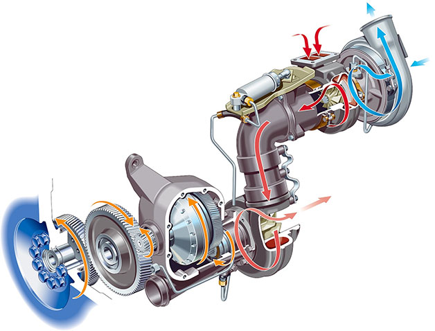
Turbo compounding is the process of using a turbo run off exhaust gasses to provide additional power to the crankshaft via gearing or a hydrodynamic coupling, or to power a generator that distributes energy via a power electronics module. The technology isn't new - the aerospace industry introduced the concept in the 1940s - but an article in Car and Driver says it could be "the next big thing in energy recovery" for automotive engines.
Turbo compounding is a way to take advantage of wasted exhaust gasses to provide more power to the engine. In the cutaway above, the compressor in the upper right (blue arrows) is powered by the turbine wheel to its left (red arrows) to send boosted intake air to the engine. The turbine, however, is also sending exhaust gas down the plumbing to its left, where another turbine connected to a shaft drives a set of gears, essentially a high-ration transmission ultimately connected to the crankshaft in the lower left.
Bowman, which engineers electrical compounding systems for power generation and heavy vehicle sectors, says its solution can increase efficiency by to seven percent with no negative impact. Mechanical compounding is said to supply gains of around five percent, but can have a negative impact depending on engine load.
Engine maker Detroit Diesel won the Truck Writers of North American Technical Achievement Award for its DD15 engine that uses mechanical compounding, and Scania and Volvo also use the tech for their truck engines. When it comes to automaker implementation, we might be looking at Formula One engine makers first: the new 1.6-liter turbo V6s use electrical compounding to run the MGU-H motor/generator to power a battery that provides extra boost during a lap.
THAAD: America's Super Shield against Ballistic Missiles?
http://nationalinterest.org/

Kazianis: For our readers who might not be familiar with THAAD or Terminal High Altitude Area Defense, could we begin by you giving TNI readers a basic description of the system and how it works? What makes it unique? Why is it in America's interest to have such a system?
Sauter: THAAD is a key element of the U.S. Ballistic Missile Defense System (BMDS) and is designed to defend U.S. troops, allied forces, population centers and critical infrastructure against short-thru-medium-range ballistic missiles. THAAD has a unique capability to destroy threats in both the endo- and exo-atmosphere using proven hit-to-kill (kinetic energy) lethality. THAAD is effective against all types of ballistic-missile warheads, especially including Weapons of Mass Destruction (chemical, nuclear or biological) payloads. THAAD was specifically designed to counter mass raids with its high firepower (up to 72 Interceptors per battery), capable organic radar and powerful battle manager/fire control capability. THAAD is interoperable with other BMDS elements, working in concert with Patriot/PAC-3, Aegis Ballistic Missile Defense, forward based sensors, and C2BMC (Command and Control, Battle Management, and Communications System) to maximize integrated air and missile defense capabilities. THAAD is mobile and rapidly deployable, which provides warfighters with greater flexibility to adapt to changing threat situations around the globe.
Kazianis: How is the system different than say PAC-3 or AEGIS systems? How is it different than other defensive systems, such as the S-300/S-400 or the Israeli Arrow?
Sauter: THAAD is the right solution today for improving ballistic-missile defense capabilities and architectures around the globe. THAAD’s unique endo & exo capability adds an essential layer of defense against current and emerging missile threats. THAAD complements existing ballistic-missile defenses by closing the battlespace gap between endo-only PAC-3 and exo-only Aegis BMD. THAAD is interoperable with all BMDS systems. As potential adversaries have continued to increase ballistic-missile inventories, THAAD provides an exceptional capability to defend against mass raids, a challenge for many ballistic-missile defense systems. THAAD is mobile and tactically transportable, providing for rapid repositioning, ensuring sustained protection against new threats while offering additional operational flexibility for high demand Aegis BMD and Patriot/PAC3 systems. THAAD has a 100 percent mission success rate in the last thirteen rigorous developmental and operational tests, including eleven for eleven successful intercepts. The most recent of these tests demonstrated the operational integration of THAAD Aegis and PAC-3 in simultaneous endo and exo atmospheric engagements of threat representative targets in an awesome display of the BMDS in action. While it is not appropriate for us to comment on other non-U.S. and non-Lockheed Martin systems, we believe that there is no other system in the world that can compare to THAAD’s unique capabilities (Endo-Exo capability against current and emerging advanced threats, hit-to-kill technology to destroy an array of missiles and payloads, extraordinary Mass-Raid capability, deployability and tactical mobility, interoperabiltiy with other BMDS elements, etc) and proven record (100 percent mission success record in nine years of rigorous developmental and complex operational BMDS testing—including 100 percent mission success and eleven for eleven intercepts, successful first operational deployment support strategic stability, delivering first <of many upcoming> THAAD foreign military sales ahead of schedule, operational readiness rate that far exceeds U.S. government standards, growing U.S. and international demand for THAAD, etc).
Kazianis: As I am sure you are quite aware, there is tremendous concern over Chinese ballistic-missile systems. How does THAAD stack up against such potential systems?
Sauter: The global proliferation of threat ballistic-missile systems, coupled with significant advances in precision, lethality and an exploitation of unprotected battlespace, requires a multitier, layered defense. To effectively defend troops, citizens, infrastructure and critical assets from these growing threats, THAAD’s unique endo & exo capability adds essential layers of defense, because it can operate in both regimes. THAAD complements existing ballistic-missile defenses by closing the battlespace gap between endo-only PAC-3 and exo-only Aegis BMD. THAAD is interoperable with all BMDS elements and provides an exceptional capability to defend against mass raids, a challenge for many ballistic-missile defense systems.
Kazianis: There does seem to be interest in foreign partners possibly purchasing the system. How would such a system benefit nations in the Asia-Pacific who face ballistic-missile challenges of their own, such as Japan, Taiwan and others?
Sauter: The U.S. government is currently executing the first THAAD foreign military sales to the United Arab Emirates, and the successful program remains ahead of schedule. There is significant international interest in THAAD, among U.S. partners around the globe, in order to better defend their people, infrastructure and critical assets against growing regional missile threats. In April 2013, the U.S. National Command Authority directed the first operational deployment of a THAAD unit in a strategic response to growing tensions in the Pacific Region. The THAAD unit remains deployed in the Pacific region today, providing a 24 x 7 defensive capability against a ballistic-missile threat that faces several U.S. international partners in the region.
Kazianis: In the last several days, there has been talk about North Korean nuclear-tipped missiles; specifically that Pyongyang could have the capability at present to place a miniaturized nuclear weapon on a long-range missile. In your view, is THAAD well positioned in its present form to handle challenges like North Korean medium or possible ICBM-style missiles?
Sauter: As we discussed earlier, THAAD’s capability was designed around addressing up to medium-range ballistic missiles, and as a result, has capability against longer-range threats, so THAAD is well positioned to handle these challenges.
Tuesday, November 18, 2014
Monday, November 17, 2014
Sunday, November 16, 2014
GT 101 gas turbine engines for use in Panther tanks
From Wikipedia, the free encyclopedia
Origins
As early as mid-1943 Adolf Müller, formerly of Junkers (Jumo) aircraft powerplant division, and then Heinkel-Hirth's (Heinkel Strahltriebwerke) jet engine division, proposed the use of a gas turbine for armored vehicle engines. A gas turbine was so much lighter than the 600 hp-class engines being used in the next-generation tanks that it would considerably improve their power-to-weight ratio and thereby improve cross-country performance, and potentially outright speed. There were problems with the gas turbine in this role, however.In the case of a jet engine the hot exhaust from the turbine is used directly for thrust, but in the case of a traction engine any heat flowing out the exhaust was essentially wasted power. The turbine exhaust was much hotter than that from a piston engine, and turbine engines would thus have terrible fuel economy compared to traditional designs. On the upside, the use of inexpensive and widely available kerosene as fuel offset this disadvantage at least to some degree, so the overall economics of running the engines might end up being similar. Given the extreme problems Germany had with fuel supplies late in the war, use of low-grade fuels, no matter how much of it was needed and used, was actually seen as a major advantage, and the primary reason the Heereswaffenamt eventually became interested in the design.
Another problem was that the gas turbine engine only works well near a particular designed operating speed, although at (or near) that speed it can provide a wide variety of output torque. More specifically, turbines offer very little torque at low speeds, which is much less of a problem for a piston engine. In order to use a turbine in this role, the design would need to use an advanced transmission and clutch that allowed the engine to run at a more limited range of speeds, or alternately use some other method to extract power.
At first the Army was uninterested, and Müller turned to the design of an advanced turbosupercharger for BMW (it is unclear if this design saw use). When this work was completed in January 1944 he once again turned to the traction engine designs, and eventually met with the Heereswaffenamt in June 1944 to present a number of proposed designs for a 1,000-horsepower unit.
Preliminary design
Müller's first detailed design was a simple modification to a traditional jet engine, the core engine being based on the experimental Heinkel HeS 011, of which only 19 complete examples were ever built. In this design a separate turbine and power take-off shaft was bolted onto the exhaust of the engine core, the hot gases of the engine powering the turbine, and thus the tank. Since the engine core was entirely separate from the power take-off, torque was available immediately because the core could be left running at full speed while generating small amounts of power, the unneeded gases being "dumped". This design had a serious problem, however; when the load was removed, during gear shifts for instance, the power turbine was unloaded and could race out of control. Either the power turbine had to be braked during these periods, or the gas flow from the engine core had to be dumped.Another problem was that the Heereswaffenamt was seriously concerned about the quality of the fuels they could find. Unlike the aviation role where it was expected the fuel would be highly refined, it was considered likely the Army would end up with lower-quality fuels that could expected to contain all sorts of heavy contaminants. This led to the possibility that the fuel would not have time to mix properly in a traditional design, leading to poor combustion. They were particularly interested in having the fuel injectors rotate along with the engine core, which could be expected to lead to much better mixing, with the additional benefit of reducing hot spots on the turbine's stators. Unfortunately Müller's design did not appear to be able to be adapted to use these injectors, and the design was eventually rejected on 12 August.
Müller then turned to designs that removed the separate power turbine and instead required some sort of torque-maintaining transmission. The best solution to the problem would have been to drive an electrical generator and use the power to drive motors for traction (a system Porsche had tried to introduce several times), but a serious shortage of copper by this point in the war — as well as its relatively poor quality throughout the war, for electrical use from sources that Germany could access — ruled out this solution. Instead some sort of hydraulic transmission was to be used, although not initially specified. Additionally, the new design included the rotating fuel injectors in the combustion chamber that the Heereswaffenamt was interested in. Müller presented the new design on 14 September, and the Heereswaffenamt proved considerably more interested – the deteriorating fuel supply situation at this point may have been a factor as well.

A preserved BMW 003 aviation engine, the basis for the GT 101 turboshaft.
Originally they had intended to mount the new engine in the Henschel-designed Tiger tank, but although the engine was smaller, in a diametral manner than the V-12 piston engine it replaced, its beginnings as the axial compressor-based BMW 003 aviation turbojet meant that it was too long to fit in the Tiger I's engine bay. Attention then turned to the Panther, which by this point in the war was to be the basis of all future tank production anyway (see the Entwicklung series for details). For experimental fitting, Porsche provided one of the prototype Jagdtiger hulls.
Fitting of the GT 101 in the Panther hull took some design effort, but eventually a suitable arrangement was found. The engine exhaust was fitted with a large divergent diffuser to lower the exhaust velocity and temperature, which also allowed for a larger third turbine stage. The entire exhaust area extended out of the rear of the engine compartment into "free air", which made it extremely vulnerable to enemy fire, and it was realized this was not practical for a production system.
A new automatic transmission from Zahnradfabrik of Friedrichshafen (ZF) was built for the fitting, it had three clutching levels in the torque converter and twelve speeds. The transmission also included an electrically-operated clutch that mechanically disengaged from the engine completely at 5,000 rpm, below which the engine produced no torque on the output. At full speed, 14,000 rpm, the engine itself also acted in the manner of a huge flywheel, which greatly improved cross-country performance by allowing some of the engine's excess speed to be dumped into the transmission to pull the tank over bumps.
In terms of performance the GT 101 would have been surprisingly effective. It would have produced a total of 3,750 hp, using 2,600 hp to operate the compressor and thus leaving 1,150 hp to power the transmission. The entire engine assembly weighted 450 kg (922 lb), not including the transmission. In comparison, the existing Maybach HL230 P30 it replaced provided 620 hp yet weighted a comparatively huge 1,200 kg. With the Maybach the Panther had a specific power of about 13.5 hp/ton, with the GT 101 this would improve to 27 hp/ton, outperforming any tank of WWII by a wide margin (for instance, the T-34 was 16.2 hp/tonne). For other reasons, essentially wear and tear, speeds would be deliberately limited to those of the gasoline-powered Panthers. The only downsides were poor torque at low power settings, and a fuel consumption about double that of the Maybach, which presented problems in finding enough room for fuel tankage — a similar problem also existed with early German gas turbines used for aircraft propulsion.
GT 102
While work on the GT 101 continued, Müller proposed another way to build the free-turbine engine that avoided the problems with his original designs. In December 1944 he presented his plans, which were accepted for development as the GT 102.The basic idea of the GT 102 was to completely separate the power turbine from the engine itself, using the latter as a gas generator. The core engine was run hot enough to power itself and nothing more, no power was taken from the core to drive the tank. Compressed air from the core's compressor, 30% of the overall airflow, was bled off through a pipe to a completely separate two-stage turbine with its own combustion chamber. This avoided the overspeed problems of the original design; when load was removed, simply shutting off the airflow to the turbine would slow it down. This also meant that the core could be run at full speed while the power turbine ran at low speed, providing significantly improved low-speed torque. The only downside to the design was that the power turbine no longer had the huge spinning mass of the GT 101, and thus did not offer any significant flywheel energy storage.
Since the turbine section of the core engine was no longer being fed all of the air from the compressor, it could be built smaller than in the GT 101. This made the engine shorter overall, allowing it to be installed transversely in the upper portion of the Panther's engine compartment, in the wider area above the tracks. The power turbine was then fitted in the empty space below, mounted at a right angle to the engine. This positioned it in-line with the normal transmission, which was located at the front of the vehicle, driving it via a power shaft. The mounting was considerably more practical than the GT 101, and entirely "under armor" as well. Although the GT 102 had fuel economy about equal to the GT 101, the mounting left considerably more empty room within the engine compartment in the space formerly used by the engine cooling system that could be used for new fuel cells, doubling the overall fuel capacity to 1,400 liters and thus providing equal range to the original gasoline engine.
Most of the design work for the GT 102 was complete by early 1945, and the plans were to have been delivered on 15 February (along with final designs for the GT 101). It appears the plans were not delivered, likely due to the deteriorating war condition.
GT 102 Ausf. 2
In order to further improve the fit of the GT 102 in the Panther, the GT 102 Ausf. 2 design modified several sections of the original gas generator layout to shorten the compressor area and combustion chamber. These were somewhat longer in the GT 102 than they would have been in a comparable aircraft engine in order to allow for better mixing with lower quality fuels. The Ausf. 2 returned these to their original dimensions, and instead re-introduced the rotating fuel injectors from the original pre-GT 101 designs. The compressor was further reduced in length by reducing it from nine to seven stages, but retained the original compression ratio by operating the first stage close to Mach 1. With these reductions in length the engine could be fit lengthwise in the engine compartment, allowing the space above the tracks to be used for fuel storage, as they had originally.GT 103
Much of the poor fuel economy of the gas turbine in the traction role was due to the hot exhaust, which essentially represented lost energy. In order to reclaim some of this energy, it is possible to use the hot exhaust to pre-heat the air from the compressor before it flows into the combustion chamber, using a heat exchanger. Although not common, these recuperators are used in a number of applications today.W. Hryniszak of Asea Brown Boveri in Heidelberg designed a recuperator that was added to the otherwise unmodified GT 102 design to produce the GT 103. The heat exchanger used a rotating porous ceramic cylinder fit into a cruciform duct. Air from the gas generator's exhaust entered the duct outside the cylinder at 500ºC, and blew around the cylinder, heating it and then exhausting at about 350 C. The ceramic cylinder rotated slowly in order to avoid overheating the "hot" side. Compressed air flowing into the power turbine was piped through the middle of the cylinder, entering at about 180 C and exiting at about 300 C.
This meant that 120 C of the 800 C final temperature of the air did not have to be provided by the fuel, representing a fairly substantial savings. Estimates suggested an improvement of about 30% in fuel consumption. It was also suggested that a second heat exchanger could be used on the gas generator engine core, saving another 30%. This reduced fuel use by half overall, making it similar to the original gasoline engine. These estimates appear unreasonable in retrospect, although General Motors did experiment with these systems throughout the 1960s and 70s.
References
- Kay, Antony, German Jet Engine and Gas Turbine Development 1930-1945, Airlife Publishing, 2002, ISBN 9781840372946
Panther II

Panther II on display at Patton Cavalry and Armor Museum, Fort Knox, KY. The turret on display was not originally fitted to this hull and was installed later.
In a meeting on 10 February 1943, further design changes were proposed - including changes to the steering gears and final drives. Another meeting on 17 February 1943 focused on sharing and standardizing parts between the Tiger II tank and the Panther 2, such as the transmission, all-steel roadwheels, and running gear. Additional meetings in February began to outline the various components, including a suggestion to use the 88 mm L/71 KwK 43 gun, however it was ultimately decided to use the 75mm KwK 42 L/70.[131] In March 1943, MAN indicated that the first prototype would be completed by August 1943. A number of engines were under consideration, among them the new Maybach HL 234 fuel-injected engine (900 hp operated by an 8-speed hydraulic transmission) and the BMW 003 aviation turbojet-derived, GT 101 gas turbine, planned to be of some 1,150 shaft horsepower output.
Thus, plans to replace the original Panther design with the Panther II were already underway before the first Panther had even seen combat. But from May to June 1943, work on the Panther II ceased as the focus was shifted to expanding production of the original Panther tank. It is not clear if there was ever an official cancellation - this may have been because the Panther II upgrade pathway was originally started at Hitler's insistence. The direction that the design was headed would not have been consistent with Germany's need for a mass-produced tank, which was the goal of the Reich Ministry of Armament and War Production.
One Panther II chassis was completed and eventually captured by the U.S.; it is now on display at the Patton Museum in Fort Knox. An Ausf G turret is mounted on this chassis.[132][133]
Panther Ausf. F
After the Panther II project died, a more limited upgrade of the Panther was planned, centered around a re-designed turret. The Ausf F variant was slated for production in April 1945, but the war ended these plans.The earliest known redesign of the turret was dated 7 November 1943 and featured a narrow gun mantlet behind a 120 mm (4.7 in) thick turret front plate. Another design drawing by Rheinmetall dated 1 March 1944 reduced the width of the turret front even further; this was the Turm-Panther (Schmale Blende) (Panther with narrow gun mantlet).[134]
Several experimental Schmaltürme (literally: "narrow turrets") were built in 1944 with modified versions of the 75 mm KwK 42 L/70, which were given the designation of KwK 44/1. A few were captured and shipped back to the U.S. and Britain. One badly damaged vehicle is on display at the Bovington Tank Museum. It had been used as a post-war range target until its historical significance was recognised.

Model of Panther Ausf. F with proposed Schmalturm
The Panther Ausf F would have had the Schmalturm, with its better ballistic protection, and an extended front hull roof which was slightly thicker. The Ausf F's Schmalturm was to have a built-in stereoscopic rangefinder and lower weight than the original turrets. A number of Ausf F hulls were built at Daimler-Benz and Ruhrstahl-Hattingen steelworks; however there is no evidence that any completed Ausf F saw service before the end of the war.
Proposals to equip the Schmalturm with the 88mm KwK 43 L/71 were made from January through March 1945. These would have likely equipped future German tanks but none were built, as the war ended.[136]
E-50
The E series of tanks — E-25, E-50, E-75, E-100 (the numbers designated their weight class) - was proposed to further streamline production with an even greater sharing of common parts and simplification of design. In this scheme, the Panther tank would have evolved into the E-50. A conical spring system was proposed to replace the complex and costly dual torsion bar system. The Schmalturm would have been used, likely with a variant of the 88 mm L/71 gun.[137]Derived vehicles

Bergepanther on display at Saumur armor museum
- Jagdpanther - heavy tank destroyer with the 88 mm L/71
- Befehlspanzer Panther - command tank with additional radio equipment
- Beobachtungspanzer Panther - observation tank for artillery spotters; dummy gun; armed with only two MG 34
- Bergepanther - armored recovery vehicle
Chrysler Turbine Car
From Wikipedia, the free encyclopedia
| Chrysler Turbine Car | |
|---|---|
 |
|
| Overview | |
| Manufacturer | Chrysler Corporation |
| Production | 1963 55 produced |
| Designer | Elwood Engel |
| Body and chassis | |
| Class | Concept car |
| Body style | 2-door coupe |
| Layout | FR layout |
| Powertrain | |
| Engine | Chrysler A831 gas turbine |
| Dimensions | |
| Wheelbase | 110 in (2,794 mm)[1] |
| Length | 201.6 in (5,121 mm)[2] |
| Width | 72.9 in (1,852 mm) |
| Height | 53.5 in (1,359 mm) (loaded) |
Project Overview
The Chrysler Turbine Car was the first and only consumer test ever conducted of gas turbine-powered cars. Of the total 55 units built (5 prototypes and 50 "production" cars), most were scrapped at the end of a trial period, with only nine remaining in museums and private collections. Though Chrysler's turbine engine project was terminated in 1977, the Turbine Car was the high point of a three decade project to perfect the engine for practical use.Engine

Engine compartment of a Chrysler 1963 Turbine car
The engine has just 1/5 of the moving parts of a traditional piston-based internal combustion engine (60 rather than 300).[5] The turbine spins on simple sleeve bearings for vibration-free running. Its simplicity offers the potential for long life, and because no combustion contaminants enter engine oil, no oil changes are considered necessary. The 1963 Turbine's engine generated 130 brake horsepower (97 kW; 132 PS) and an instant 425 pound force-feet (576 N·m) of torque at stall speed, making it good for 0 to 60 mph (0 to 97 km/h) in 12 seconds at an ambient temperature of 85 °F (29 °C)—it can sprint quicker if the ambient air was cooler and denser.
The lack of many moving parts and the lack of liquid coolant eases maintenance, while the exhaust does not contain carbon monoxide, unburned carbon, or raw hydrocarbons. Nevertheless, the turbine generates nitrogen oxides and the challenge of limiting them proved an ongoing problem throughout development.
The power turbine is connected, without a torque converter, through a gear reduction unit to an only moderately modified TorqueFlite automatic transmission. The flow of the combustion gases between the gas generator and free power turbine provides the same functionality as a torque converter but without using a conventional liquid medium. Twin rotating recuperators transfer exhaust heat to the inlet air, greatly improving fuel economy. Varying stator blades prevent excessive top end speeds, and provide engine braking on deceleration.
Throttle lag and exhaust gas temperatures at idle plague early models; Chrysler was able to remedy or mitigate these to some degree. Acceleration lag, however, remains a problem, and fuel consumption is excessive. Acceleration is outstanding provided the turbine is spun up (by applying power) prior to releasing the brakes. Otherwise it is mediocre. The Turbine Car also features a fully stainless steel exhaust system, the exits of which are flat in cross section. This was intended to spread the exhaust gases thinly and thus cool them further, in order to allow the vehicle to stand in traffic without risking damage to following traffic. The combustor, or burner, is somewhat primitive by the standards of modern turbojet engines. A single reverse-flow canister featuring a more-or-less standard spark plug for ignition is employed. Had the engine been further developed, annular combustion chambers along with a second power turbine might have improved power and economy even more. The transmission has "idle" instead of "neutral".[6]
The turbine car has some operational and aesthetic drawbacks. The car sounds like a giant vacuum cleaner, which was unexpected to consumers who were more familiar with the sound of a large American V8. That said, some observers admired the sound. High altitudes also cause problems for the combined starter-generator. Additionally, failing to follow the correct start-up procedure will cause the engine to stall; some drivers thought they could warm up the engine similar to the way they did with a gasoline engine. They would press the accelerator pedal to the floor before the engine had reached proper temperature. Instead of warming the engine, the excess fuel slowed the turbine down and resulted in the opposite of the desired effect. Doing this, however, did not do any permanent damage to the engine. In fact, it was possible to apply full throttle immediately after starting the engine without much fear of excessive wear. The engines were remarkably durable considering how fragile turbine engines are when compared to internal combustion piston engines. Troubles were remarkably few for such a bold experiment. It is not known how many testers made the mistake of using the leaded pump gas of the era; the tetraethyl lead leaves debilitating deposits within the engine. It was the one flammable liquid Chrysler recommended not be used; it was also by far the easiest fuel to obtain. Even so, more than 1.1 million test miles were accumulated by the 50 cars given to the public, and operational downtime stood at only 4%.
Design

Chrysler Turbine Car at the 1964 New York World's Fair
The Turbine Car is a two-door hardtop coupe with four individual bucket seats, power steering, power brakes, and power windows. Its most prominent design features are two large horizontal taillights and nozzles (back-up lights) mounted inside a very heavy chrome sculptured bumper. Up front, the single headlamps are mounted in chrome nacelles with a turbine styling theme, creating a striking appearance. This theme is carried through to the center console and the hubcaps. Even the tires were specially made with small turbine vanes molded into the white sidewalls. It is finished in reddish-brown "Frostfire Metallic" paint, later renamed "Turbine Bronze" and made available on production automobiles. The roof is covered in black vinyl, and the interior features bronze-colored "English calfskin" leather upholstery with plush-cut pile bronze-colored carpet. Front suspension is upper and lower wishbones with coil springs and shock absorbers.[1]
The dashboard is lit using electroluminescent panels in the gauge pods and on a call-out strip across the dash. This system did not use bulbs; instead, an inverter and transformer raised the battery voltage to over 100 volts AC and passed that high voltage through special plastic layers, causing the gauges to glow with a blue-green light. Instead of a water temp. gauge, the Chrysler Turbine has a Turbine Inlet temp. gauge with numbers 500, 1,000, 1,500, and 2,000 degrees Fahrenheit.[10]
The car itself was designed in the Chrysler studios under the direction of Elwood Engel, who had worked for the Ford Motor Company before his move to Chrysler. The designer credited with the actual look of the car was Charles Mashigan, who designed a two-seat show car called the Typhoon,[11] which was displayed at the 1964 World's Fair in New York City. Engel used many older Ford styling themes. The rear taillight/bumper assembly was copied directly (with revisions) from a 1958 Ford styling study called the "La Galaxie". He used none of the themes associated with his 1964 Imperial. As Engel incorporated many of the design themes from the 1961 Thunderbird, and because the car was a four seater of similar size and appointment, many enthusiasts call the Ghia Turbine the "Englebird."
Suspension did not follow Chrysler's ubiquitous independent front longitudinal torsion bar system of the time, but rather featured contemporary designs using independent front suspension with a coil spring at each wheel. Rear suspension was more typical of Chrysler, with leaf springs and direct-acting shock absorbers.
Legacy

Chrysler Turbine Car at the 1999 Antique Automobile Club of America show in Hershey, PA
Of the remaining nine cars, six had the engines de-activated and then they were donated to museums around the country. Chrysler retained three operational turbine cars for historical reasons; two of the three are now owned by the "WPC Museum". All of the turbine cars owned by the "WPC Museum" are in running condition at the archives of the museum. The last turbine car that is functional, owned by the Museum of Transportation in St. Louis, was photographed for Mopar Action magazine, and appears at car shows around the United States from time to time. One Turbine car is on display at The Henry Ford Museum in Dearborn, Michigan, and it was be part of the exhibition Driving America in early 2012.
Only two Chrysler Turbine Cars are in the hands of private collectors: One was purchased by private automobile collector Frank Kleptz of Terre Haute, Indiana and is functional. Kleptz's Turbine Car was originally donated to the former Harrah museum in Nevada. The second one is owned by comedian and television host Jay Leno, who purchased one of the three Chrysler Turbine Cars which had been originally retained by Chrysler.[12] Leno wrote that
- Most were destroyed by Chrysler for tax and liability reasons, which is a shame, because to this day everyone who rides in a Turbine says, "Whoa, this feels like the future!" You turn the key and there's a big woosh and a complete absence of vibration... I think it's the most collectible American car—it was so different. Most of all, the Chrysler Turbine is a reminder that all the cool stuff used to be made in the U.S. I hope it will be again.[13]
A smaller, lighter seventh generation engine was produced in the early 1970s, when the company received a grant from the United States Environmental Protection Agency (EPA) for further development, and a special bodied turbine Chrysler LeBaron was built in 1977 as a prelude to a production run. By then the company was in dire financial straits and needed U.S. government loan guarantees to avoid bankruptcy. A condition of that deal was that gas-turbine mass production be abandoned because it was "too risky" for an auto company of Chrysler's size.
A Chrysler Turbine Car, painted white with blue racing stripes, featured in the 1964 film The Lively Set. The car, loaned to the producers by Chrysler, was one of the test 'mules', and was returned to Chrysler after production. It was among the cars scrapped.[citation needed]
While Chrysler's work with turbine engines never paid off in the retail automobile sector, the experiments proved fruitful with the incorporation of a Honeywell AGT1500 into a slightly different product, the M1 Abrams Main Battle Tank, developed in the late 1970s by Chrysler Defense (which was later sold to General Dynamics).
Recuperator
From Wikipedia, the free encyclopedia

Contents
Description
In many types of processes, combustion is used to generate heat, and the recuperator serves to recuperate, or reclaim this heat, in order to reuse or recycle it. The term recuperator refers as well to liquid-liquid counterflow heat exchangers used for heat recovery in the chemical and refinery industries and in closed processes such as ammonia-water or LiBr-water absorption refrigeration cycles.Recuperators are often used in association with the burner portion of a heat engine, to increase the overall efficiency. For example, in a gas turbine engine, air is compressed, mixed with fuel, which is then burned and used to drive a turbine. The recuperator transfers some of the waste heat in the exhaust to the compressed air, thus preheating it before entering the fuel burner stage. Since the gases have been pre-heated, less fuel is needed to heat the gases up to the turbine inlet temperature. By recovering some of the energy usually lost as waste heat, the recuperator can make a heat engine or gas turbine significantly more efficient.
Energy transfer process
Normally the heat transfer between airstreams provided by the device is termed as 'sensible', which is the exchange of energy, or enthalpy, resulting in a change in temperature of the medium (air in this case), but with no change in moisture content. However, if moisture or relative humidity levels in the return air stream are high enough to allow condensation to take place in the device, then this will cause 'latent' heat to be released and the heat transfer material will be covered with a film of water. Despite a corresponding absorption of latent heat, as some of the water film is evaporated in the opposite airstream, the water will reduce the thermal resistance of the boundary layer of the heat exchanger material and thus improve the heat transfer coefficient of the device, and hence increase efficiency. The energy exchange of such devices now comprises both sensible and latent heat transfer; in addition to a change in temperature, there is also a change in moisture content of the exhaust air stream.However, the film of condensation will also slightly increase pressure drop through the device, and depending upon the spacing of the matrix material, this can increase resistance by up to 30%. If the unit is not laid to falls, and the condensate not allowed to drain properly, this will increase fan energy consumption and reduce the seasonal efficiency of the device.
Use in ventilation systems
In heating, ventilation and air-conditioning systems, HVAC, recuperators are commonly used to re-use waste heat from exhaust air normally expelled to atmosphere. Devices typically comprises a series of parallel plates of aluminium, plastic, stainless steel, or synthetic fibre, alternate pairs of which are enclosed on two sides to form twin sets of ducts at right angles to each other, and which contain the supply and extract air streams. In this manner heat from the exhaust air stream is transferred through the separating plates, and into the supply air stream. Manufacturers claim gross efficiencies of up to 80% depending upon the specification of the unit.The characteristics of this device are attributable to the relationship between the physical size of the unit, in particular the air path distance, and the spacing of the plates. For an equal air pressure drop through the device, a small unit will have a narrower plate spacing and a lower air velocity than a larger unit, but both units may be just as efficient. Because of the cross-flow design of the unit, its physical size will dictate the air path length, and as this increases, heat transfer will increase but pressure drop will also increase, and so plate spacing is increased to reduce pressure drop, but this in turn will reduce heat transfer.
As a general rule a recuperator selected for a pressure drop of between 150 and 250Pa will have a good efficiency, whilst having a small effect on fan power consumption, but will have in turn a higher seasonal efficiency than that for physically smaller, but higher pressure drop recuperator.
When heat recovery is not required, it is typical for the device to be bypassed by use of dampers arranged within the ventilation distribution system. Assuming the fans are fitted with inverter speed controls, set to maintain a constant pressure in the ventilation system, then the reduced pressure drop leads to a slowing of the fan motor and thus reducing power consumption, and in turn improves the seasonal efficiency of the system.
Use in metallurgical furnaces
Recuperators have also been used to recover heat from waste gasses to preheat combustion air and fuel for many years by metallic recuperators to reduce energy costs and carbon footprint of operation. Compared to alternatives such as regenerative furnaces, initial costs are lesser, there are no valves to be switching back and forth, there are no induced-draft fans and it does not require a web of gas ducts spread up all over the furnace.Historically the recovery ratios of recuperators compared to regenerative burners were low. However, recent improvements to technology have allowed recuperators to recover 70-80% of the waste heat and pre-heated air up to 850-900 deg C is now possible.
Use in microturbines
Recuperators can be used to increase the efficiency of gas turbines for power generation, provided the exhaust gas is hotter than the compressor outlet temperature. The exhaust heat from the turbine is used to pre-heat the air from the compressor before further heating in the combustor, reducing the fuel input required. The larger the temperature difference between turbine out and compressor out, the greater the benefit from the recuperator. [1] Therefore, microturbines (<1MW), which typically have low pressure ratios, have the most to gain from the use of a recuperator. In practice, a doubling of efficiency is possible through the use of a recuperator.[2] The major practical challenge for a recuperator in microturbine applications is coping with the exhaust gas temperature, which can exceed 750C.


Mopar has always been known for its engineering superiority like the HEMI engine, with its amazing flow rate and rev happy shaft rocker arm heads. And Chrysler had a lot of challenges with the turbine, chief among them acceleration lag—the time it takes the rotating assembly to reach target RPM after the accelerator pedal is depressed. The first generation of engines reportedly had lag on the order of six to seven seconds, not exactly a good experience for a street driver. By the third generation, the one that powered the Turbine car the select few members of the public got to drive, that was down to one or one-and-a-half-seconds.
One of the main design features of the engine that greatly contributed to making it streetable was Chrysler’s breakthrough heat exchanger—the regenerator. The regenerator was a rotating assembly with its axis perpendicular to the axis of the main engine shaft. There were two regenerators located on the left and right side of the engine. You can think of the regenerator as a thermal water wheel, only instead of carrying water from the bottom to the top of the wheel, the regenerator rotor carried heat energy from the back of the engine to the front. The purpose of the regenerator was to extract energy from the hot exhaust gases and transfer that energy into the relatively cool air exiting the compressor. Heating the air from the compressor before it entered the combustion chamber greatly reduced the amount of fuel that needed to be burned within the combustor to achieve optimal combustion temperature. If you think about it, the whole purpose of an engine is to create heat so that expanding combustion gases can be turned into mechanical energy.
Long before hybrid cars were about recycling energy from braking into electricity that is stored in a battery and recalled by an electric engine during acceleration, the Chrysler turbine regenerator was recycling energy from the exhaust gases into the intake air for acceleration and fuel mileage boost. The regenerator carried the heat energy 180 degrees from exhaust path to the pre-combustion air path. The greatly cooled regenerator then traveled another 180 to complete the 360 degree cycle where it would start over again. And the amount of energy that can be converted into and out of the regenerator rotor is really astounding. 500-700 degrees of heat would be added to the regenerator and then passed into the intake air as the rotor cooled by the same amount, all happening within a tiny fraction of a second as the regenerator spun. By the third generation of engine, as used in the Turbine car, the regenerator was recycling almost 90% of the heat energy in the exhaust gases. Really amazing
Honeywell AGT1500
From Wikipedia, the free encyclopedia
| AGT1500 | |
|---|---|
 |
|
| U.S. Marines load an AGT1500 engine back into an M1A1 Abrams tank at Camp Coyote, Kuwait in February 2003. | |
| Type | Turboshaft gas turbine |
| National origin | United States |
| Manufacturer | Lycoming Engines Honeywell Aerospace |
| Major applications | M1 Abrams |
| Developed into | GE/Honeywell LV100 |
Engine output peaks at 1,500 hp (1,120 kW), with 2,750 lb-ft (3,754 N-m) of torque at that peak.[2] The engine can use a variety of fuels, including jet fuel, gasoline, diesel and Marine Diesel.[2]
During the early 1970s, the AGT1500 was developed into the PLT27, a flight-weight turboshaft for use in helicopters. This engine lost to the General Electric GE12 (T700) in three separate competitions to power the UH-60, AH-64, and SH-60.[3]
M1 Abrams
From Wikipedia, the free encyclopedia
"M1 Tank" redirects here. For the early 20th Century light tank, see M1 Combat Car.
The M1 Abrams entered U.S. service in 1980, replacing the M60 tank.[12] It served for over a decade alongside the improved M60A3, which had entered service in 1978. The M1 remains the principal main battle tank of the United States Army and Marine Corps, and the armies of Egypt, Kuwait, Saudi Arabia, Australia and Iraq.
Three main versions of the M1 Abrams have been deployed, the M1, M1A1, and M1A2, incorporating improved armament, protection and electronics. These improvements, as well as periodic upgrades to older tanks, have allowed this long-serving vehicle to remain in front-line service. The M1A3 was under early development as of 2009.[13]
Contents
History
Main article: History of the M1 Abrams
The M1 Abrams was developed during the Cold War as a successor to the canceled MBT-70. The M1 Abrams contract went to Chrysler Defense and was the first vehicle to adopt Chobham armor. Adaptations before the Persian Gulf War
(Operations Desert Shield and Desert Storm) gave the vehicle better
firepower and NBC (Nuclear, Biological and Chemical) protection. Being
vastly superior to Iraqi tanks, very few M1 tanks were hit by enemy
fire. Upgrades after the war improved the tank's weapons sights and fire
control unit. The invasion of Iraq in 2003 destroyed Iraq's military.
The subsequent insurgency exposed the tanks' vulnerability to rocket-propelled grenades and mines. These problems were partially rectified with the TUSK modification. The Marine Corps sent a company of M1A1 Abrams to Afghanistan in late 2010.Development
The first attempt to replace the aging M60 tank was the MBT-70, developed in partnership with West Germany in the 1960s. The MBT-70 had advanced features such as a height-adjustable pneumatic suspension and a very small body with the driver in a turret design that allowed the driver to always face the direction of travel. The MBT-70 ultimately proved to be too heavy, complex, and expensive. As a result of the imminent failure of this project, the U.S. Army introduced the XM803, using some technologies from the MBT-70 but removing some of the more troublesome. This succeeded only in producing an expensive system with capabilities similar to the M60.[14]
An XM1 Abrams, during a demonstration at Fort Knox, Kentucky in 1979
|
| M1 Abrams | |
|---|---|
 |
|
| Type | Main battle tank |
| Place of origin | United States |
| Service history | |
| In service | 1980–present |
| Used by | See Operators below |
| Wars | Gulf War War in Afghanistan Iraq War |
| Production history | |
| Designer | Chrysler Defense (now General Dynamics Land Systems) |
| Designed | 1972–79 |
| Manufacturer | Lima Army Tank Plant (since 1980)[2] Detroit Arsenal Tank Plant (1982–1996) |
| Unit cost | US$6.21 million (M1A2 / FY99)[3] Estimated in 2012 as US$8.58 million (with inflation adjustment) |
| Produced | 1979–present |
| Number built | 9,000+[4] |
| Variants | See variants |
| Specifications | |
| Weight | M1: 60 short tons (54 long tons; 54 t)[5] M1A1: 63 short tons (56 long tons; 57 t)[5] M1A2: 68 short tons (61 long tons; 62 t) |
| Length | Gun forward: 32.04 ft (9.77 m)[6] Hull length: 26.02 ft (7.93 m) |
| Width | 12 ft (3.66 m)[6] |
| Height | 8 ft (2.44 m)[6] |
| Crew | 4 (commander, gunner, loader, driver) |
| Armor | M1, M1A1: Burlington composite armor[7] M1A2: depleted uranium mesh-reinforced composite armor[7] |
Main
armament |
M1: 105 mm L/52 M68 rifled gun (55 rounds) M1A1: 120 mm L/44 M256A1 smoothbore gun (40 rounds) M1A2: 120 mm L/44 M256A1 smoothbore gun (42 rounds) |
Secondary
armament |
1 × .50-caliber (12.7 mm) M2HB heavy machine gun with 900 rounds 2 × 7.62 mm (.308 in) M240 machine guns with 10,400 rounds (1 pintle-mounted, 1 coaxial) |
| Engine | Honeywell AGT1500C multi-fuel turbine engine 1,500 shp (1,120 kW) |
| Power/weight | From 26.9 hp/t (20.05 kW/t) to 23.8 hp/t (17.74 kW/t) |
| Transmission | Allison DDA X-1100-3B |
| Suspension | High-hardness-steel torsion bars with rotary shock absorbers |
| Ground clearance | M1, M1A1: 0.48 m (1 ft 7 in) M1A2: 0.43 m (1 ft 5 in) |
| Fuel capacity | 500 US gallons (1,900 l; 420 imp gal) |
Operational
range |
M1A2: 426 km (265 mi)[10] |
| Speed | M1A1: Road 45 mph (72 km/h) (governed); Off-road: 30 mph (48 km/h)[6] M1A2: Road 42 mph (67 km/h) (governed); Off-road: 25 mph (40 km/h)[10] |
A total of 3,273 M1 Abrams were produced 1979–85 and first entered U.S. Army service in 1980. Production at the government-owned, GDLS-operated Lima Army Tank Plant in Lima, Ohio, was joined by vehicles built at the Detroit Arsenal Tank Plant in Warren, Michigan from 1982 to 1996.[2] The M1 was armed with the license-built version of the 105 mm Royal Ordnance L7 gun. An improved model called the M1IP was produced briefly in 1984 and contained small upgrades. The M1IP models were used in the Canadian Army Trophy NATO tank gunnery competition in 1985 and 1987.

105-mm M1 Abrams tank of the 11th Armored Cavalry Regiment at Grafenwöhr Training Area in Germany, 1986
In 1990, Project on Government Oversight in a report criticized the M1's high costs and low fuel efficiency in comparison with other tanks of similar power and effectiveness such as the Leopard 2. The report was based on data from U.S. Army sources and the Congressional record.[15]
As the Abrams entered service in the 1980s, they operated alongside M60A3 within the United States military, and with other NATO tanks in numerous Cold War exercises. These exercises usually took place in Western Europe, especially West Germany, but also in some other countries, including South Korea. The exercises were aimed at countering Soviet forces. However, by January 1991 the Berlin Wall had fallen and the Abrams was instead employed in the Middle East.
Gulf War

Abrams move out on a mission during Desert Storm in 1991. A Bradley IFV and logistics convoy can be seen in the background.

A destroyed M1A1, lost to friendly fire.
During Operations Desert Shield and Desert Storm some M1IP and M1A1s were modified locally in theater by modification work orders (MWO) with additional rolled homogenous armor plating welded on the turret front. The M1 can be equipped with mine plow and mine roller attachments.
Upgrades
The M1A2 was a further improvement of the M1A1 with a commander's independent thermal viewer, weapon station, position navigation equipment, and a full set of controls and displays linked by a digital data bus. These upgrades also provided the M1A2 with an improved fire control system.[19] The M1A2 System Enhancement Package (SEP) added digital maps, FBCB2 capabilities, and an improved cooling system to compensate for heat generated by the additional computer systems. The M1A2 SEP also serves as the basis for the M104 Wolverine heavy assault bridge. The M1A2 SEPv2 (version 2) added Common Remotely Operated Weapon Station (CROWS or CROWS II) support, color displays, better interfaces, a new operating system, better front and side armor, and an upgraded transmission for better durability.[20] Further upgrades included depleted uranium armor for all variants, a system overhaul that returns all A1s to like-new condition (M1A1 AIM), a digital enhancement package for the A1 (M1A1D), and a commonality program to standardize parts between the U.S. Army and the Marine Corps (M1A1HC).Iraq War

M1A1 conducts reconnaissance in Iraq, September 2004.
The most lopsided achievement of the M1A1s was the destruction of seven T-72s in a point-blank skirmish (less than 50 yards (46 m)) near Mahmoudiyah, about 18 miles (29 km) south of Baghdad, with no losses for the American side.[22] In addition to the Abrams's already heavy armament, some crews were also issued M136 AT4 shoulder-fired anti-tank weapons under the assumption that they might have to engage heavy armor in tight urban areas where the main gun could not be brought to bear.

U.S. Army M1A2 Abrams with TUSK equipment

Abrams crossing the Euphrates River at Objective Peach on ribbon assault float bridge deployed by the 299th Engineer Company in 2003.

M1 Abrams destroyed in Iraq, 2003
Due to the vulnerability of tanks in urban combat, the Tank Urban Survival Kit (or TUSK) is being issued to some M1 Abrams. It adds protection in the rear and side of the tank to improve fighting ability in urban environments.[28]
In May 2008, it was reported that an American M1 tank had also been damaged by an RPG-29, which uses a tandem-charge high explosive anti-tank warhead to penetrate explosive reactive armor (ERA) as well as composite armor behind it, in Iraq.[29][30] The U.S. considered the RPG-29 threat to American armor high and refused to allow the newly formed Iraqi Army to buy it, fearing that it would fall into the insurgents' hands.[31]
In mid-2014, the Abrams tank saw action in Iraq when the Islamic State launched the June 2014 Northern Iraq offensive. Some Iraqi Army M1A1M tanks were destroyed in fighting against ISIL forces, while an unknown number were captured intact.[citation needed] At least one ISIL-controlled M1A1M Abrams was reportedly used in the Battle for Mosul Dam in early August 2014.[citation needed]
War in Afghanistan
Operating tanks in Afghanistan can be difficult due to the rough terrain, although Canada and Denmark have deployed Leopard 1 and 2 battle tanks that have been specially modified to operate in the relatively flat and arid conditions of south-western Afghanistan. In late 2010, at the request of Regional Command Southwest, the U.S. Marine Corps deployed a small detachment of 14 M1A1 Abrams from Delta Company, 1st Tank Battalion, 1st Marine Division (Forward),[32] to southern Afghanistan in support of operations in Helmand and Kandahar provinces.[33]Future
The tracked M8 Armored Gun System was conceived as a possible supplement for the Abrams in U.S. service for low-intensity conflict in the early 1990s. Prototypes were made but the program was canceled. The 8-wheeled M1128 Mobile Gun System was designed to supplement the Abrams in U.S. service for low-intensity conflict.[34] It has been introduced into service and serves with Stryker brigades and Airborne units.The U.S. Army's Future Combat Systems XM1202 Mounted Combat System was to replace the Abrams in U.S. service and was in development when funding for the program was cut from the DoD's budget.
The M1A3 Abrams was in the early design period with the U.S. Army in 2009. At that time, the service was seeking a lighter tank version with the same protection as current versions. It aimed to build prototypes by 2014 and begin fielding the first combat-ready M1A3s by 2017.[13][35] With the budget compromise of December 2013, the M1A3 program is expected to receive funding needed to begin full-scale production in 2018.[citation needed]
The M1A2 SEP TUSK Abrams and a modernized M1 Abrams were included in the Ground Combat Vehicle (GCV) Analysis of Alternatives (AOA). Vehicles included in the AOA were determined to be inferior to the planned GCV.[36] The U.S. Army Vice Chief of Staff Gen. Peter Chiarelli commended the M1 Abrams program and recommended a similar approach for the GCV program.[37] The Ground Combat Vehicle family of vehicles is the planned successor to the M1 as well as many other U.S. Army vehicles. However, the Army anticipates that the remaining M1A1 fleet will remain in U.S. service until at least 2021, and the M1A2 to beyond 2050.[38]
Production shutdown
The U.S. Army planned to end production at the Lima Army Tank Plant from 2013 to 2016 in an effort to save over $1 billion; it would be restarted in 2017 to upgrade existing tanks. General Dynamics Land Systems (GDLS), which operates the factory, opposed the move, arguing that suspension of operations would increase long-term costs and reduce flexibility.[39][40] Specifically, GDLS estimated that closing the plant would cost $380 million and restarting production would cost $1.3 billion.[41] If passed, a bill in the U.S. Senate from the first session of the 112th Congress would allocate $272 million in funds toward the plant to allow it to continue regular operations through 2013.[42]By 16 August 2013, details emerged on how the $181 million Congress had allocated for the Abrams would be spent: $114 million would upgrade 12 tanks, $26 million would buy 48 transmissions, and $41 million would buy 86 Block II second-generation forward-looking infrared sensors. The buy is to mitigate Abrams FLIR industrial base risks, and sustain development and production capability. Congress and General Dynamics had been criticized for redirecting money to keep production lines open. A report in July 2012 documented that the company and its employees gave campaign donations to lawmakers, and over 120 lawmakers sent a letter to Secretary of the Army John McHugh expressing their disappointment that the service had stated they didn't intend to fund any tank upgrades until 2017. General Dynamics had asserted that a four-year shutdown would cost $1.1–1.6 billion when the time came to restart the line. The difference between the estimates was because of several variables, including the length of the shutdown, whether the Army would pay to keep machinery oiled and running periodically, and whether the plant's components would be completely removed. The company and Congress were accused of "forcing the Army to buy tanks it didn't need." The fleet age is low and the Army is not required to begin recapitalization until FY 2017, believing that foreign sales can keep the line running until then. General Dynamics contends that they are not forcing more tanks onto the Army, but that they are changing their configuration to make them the most modern. At the time, most Army National Guard units operated the M1A1, while only two Guard units and the rest of the Army had upgraded versions. The 12 upgraded tanks will be going to the National Guard to expand a "pure fleet." The Army has identified three key "irreplaceable" subcomponents: Allison transmissions, Honeywell turbine engines, and night vision systems for target acquisition. Makers of those subcomponents were not in danger of going out of business, but a prolonged shutdown could cause them to lose their ability to produce them. Foreign sales are also not certain to keep orders, as planned contracts from Saudi Arabia, Morocco, Iraq, and Egypt have been pushed back or are unknown. Even though money is being spent to protect the industrial base, some feel those strategic choices should not be made by members of Congress, especially those with the facilities in their district. There is still risk of production gaps even with production extended through 2015. With funds awarded before recapitalization is needed, budgetary pressures may push planned new upgrades for the Abrams from 2017 to 2019.[43]
Design
Countermeasures
Camouflage

American M1A1s during the Foal Eagle 1998 training exercises in South Korea, with their factory single green paint scheme.

M1A1 in the Australian Army's Disruptive Pattern Camouflage, used for
vehicles and materiel. Smoke grenade launchers are seen at left.
M1A1s came from the factory with the NATO three color camouflage Black/Med-Green/Dark-Brown CARC paint jobs.[citation needed] Today M1A1s are given the NATO three color paint job during rebuilds. M1s and M1A1s deployed to Desert Storm were hastily painted desert tan. Some, but not all, of these tanks were re-painted to their "authorized" paint scheme. M1A2s built for Middle Eastern countries were painted in desert tan. Some M1 series tanks are being painted desert tan for service in Iraq and some are not. Replacement parts (roadwheels, armor skirt panels, drive sprockets, etc.) are painted overall green, which can sometimes lead to vehicles with a patchwork of green and desert tan parts.
Australian M1A1s were desert tan when delivered but have undergone a transition to the Australian Army vehicle standard 'Disruptive Pattern Camouflage'; a scheme that consists of black, olive drab and brown.[44][45]
Concealment
The turret is fitted with two six-barreled smoke grenade launchers (USMC M1A1s use an eight-barreled version). These can create a thick smoke that blocks both vision and thermal imaging. The engine is also equipped with a smoke generator that is triggered by the driver. When activated, fuel is sprayed into the hot turbine exhaust, creating the thick smoke. However, due to change from diesel as a primary fuel to the use of JP-8, this system is disabled on most Abrams today because of a slightly elevated risk of fire damage to the engine compartment.Active protection system
In addition to the armor, some Abrams are equipped with a Softkill Active protection system, the AN/VLQ-6 Missile Countermeasure Device (MCD) that can impede the function of guidance systems of some semi-active control line-of-sight (SACLOS) wire and radio guided anti-tank missiles (such as the Russian 9K114 Shturm) and thermally and infrared guided missiles.[46] The MCD works by emitting a massive, condensed infrared signal to confuse the seeker of an anti-tank guided missile (ATGM). However, the drawback to the system is that the ATGM is not destroyed, it is merely directed away from its intended target, leaving the missile to detonate elsewhere. This device is mounted on the turret roof in front of the loader's hatch, and can lead some people to mistake Abrams fitted with these devices for the M1A2 version, since the Commander's Independent Thermal Viewer on the latter is mounted in the same place, though the MCD is box-shaped and fixed in place as opposed to cylindrical and rotating like the CITV.Armor

Beginning in 1987, M1A1 tanks received improved armor packages that incorporated depleted uranium (DU) components in their armor at the front of the turret and the front of the hull. Armor reinforced in this manner offers significantly increased resistance towards all types of anti-tank weaponry, but at the expense of adding considerable weight to the tank, as depleted uranium is 1.7 times more dense than lead.[47] The first M1A1 tanks to receive this upgrade were tanks stationed in Germany, since they were the first line of defense against the Soviet Union. US-based tank battalions participating in Operation Desert Storm received an emergency program to upgrade their tanks with depleted uranium armor immediately before the onset of the campaign. M1A2 tanks uniformly incorporate depleted uranium armor, and all M1A1 tanks in active service have been upgraded to this standard as well. The added protection from the depleted uranium armor is believed to be equivalent to 24 inches (610 mm) of RHA. In the Persian Gulf War, Abrams tanks survived multiple hits at relatively close ranges from Iraqi Lion of Babylon tanks and ATGMs. M829A1 "Silver Bullet" APFSDS rounds from other M1A1 Abrams were unable to penetrate the front and side armor (even at close ranges) in friendly fire incidents as well as an incident in which an Abrams tried to destroy an abandoned Abrams stuck in the mud.[48]
Damage control
The tank has a halon firefighting system to automatically extinguish fires in the crew compartment. The engine compartment has a firefighting system that is engaged by pulling a T-handle located on the left side of the tank. The crew compartment also contains small hand-held fire extinguishers. Fuel and ammunition are stored in armored compartments with blowout panels to protect the crew from the risk of the tank's own ammunition cooking off if the tank is damaged — the main gun's ammunition is stored in the rear section of the turret, with blast doors that open under power by sliding sideways only to remove a round for firing, then automatically close.Armament
Primary
- M68A1 rifled gun
- M256 smoothbore gun

A Marine M1A1 fires its main gun into a house providing suppressive counter fire against insurgents in Iraq during the Second Battle of Fallujah, 2004.
The M256A1 fires a variety of rounds. The M829A2 APFSDS round was developed specifically to address the improved protection of a Russian T-72, T-80U or T-90 main battle tank equipped with Kontakt-5 Explosive Reactive Armor.[49] Later, the M829A3 APFSDS round was introduced to improve its effectiveness against next generation ERA equipped tanks. As a counter to that, the Russian army introduced Relikt, the most modern Russian ERA, which is claimed to be twice as effective as Kontakt-5.[50] Development of the M829 series is continuing with the M829E4 currently in development.[51] The Abrams also fires HEAT shaped charge rounds such as the M830, the latest version of which (M830A1) incorporates a sophisticated multi-mode electronic sensing fuse and more fragmentation which allows it to be used effectively against armored vehicles, personnel, and low-flying aircraft. The Abrams uses a manual loader. The fourth tank crew member on the Abrams also provides additional support for maintenance, observation post/listening post (OP/LP) operations, and other tasks.
The new M1028 120 mm anti-personnel canister cartridge was brought into service early for use in the aftermath of the 2003 invasion of Iraq. It contains 1,098 3⁄8-inch (9.5 mm) tungsten balls which spread from the muzzle to produce a shotgun effect lethal out to 600 meters (2,000 ft). The tungsten balls can be used to clear enemy dismounts, break up hasty ambush sites in urban areas, clear defiles, stop infantry attacks and counter-attacks and support friendly infantry assaults by providing covering fire. The canister round is also a highly effective breaching round and can level cinder block walls and knock man-sized holes in reinforced concrete walls for infantry raids at distances up to 75 meters (246 ft).[52] Also in use is the M908 obstacle-reduction round. It is designed to destroy obstacles and barriers. The round is a modified M830A1 with the front fuse replaced by a steel nose to penetrate into the obstacle before detonation.[53]
The Army is developing a new round to replace the M830/M830A1, M1028, and M908. Called the Advanced Multi-Purpose (AMP) round, it will have point detonation, delay, and airburst modes through an ammunition data link and a multi-mode, programmable fuse in a single munition. Having one round that does the job of four would simplify logistics and be able to be used on a variety of targets. The AMP is to be effective against bunkers, infantry, light armor, and obstacles out to 500 meters, and will be able to breach reinforced concrete walls and defeat ATGM teams from 500 to 2,000 meters.[54][55]
In addition to these, the XM1111 (Mid-Range-Munition Chemical Energy) was also in development. The XM1111 was a guided munition using a dual-mode seeker that combined imaging-infrared and semi-active laser guidance. The MRM-CE was selected over the competing MRM-KE which used a rocket-assisted kinetic energy penetrator. The CE variant was chosen due to its better effects against secondary targets, providing a more versatile weapon. The Army hoped to achieve IOC with the XM1111 by 2013.[56] However, the Mid-Range Munition was cancelled in 2009 along with Future Combat Systems.[57]
Secondary

M1A1 firing its main gun as seen from the loader's hatch. The M240 is visible left while the M2HB is visible right.
- A .50 cal. (12.7 mm) M2HB machine gun in front of the commander's hatch. On the M1, M1A1, and M1A2 this gun is mounted on the Commander's Weapons Station. This allows the weapon to be aimed and fired from within the tank. With the Common Remote Operated Weapons System (CROWS) add-on kit, an M2A1 .50 Caliber Machinegun, M240, or M249 SAW can be mounted on a CROWS remote weapons platform (similar to the Protector M151 remote weapon station used on the Stryker family of vehicles). Current variants of the TUSK kit on the M1A2 have forgone this, instead adding transparent gun shields to the commander's weapon station. The upgrade variant called M1A1 Abrams Integrated Management (AIM) equips the .50 caliber gun with a thermal sight for accurate night and other low-visibility shooting.[58]
- A 7.62 mm M240 machine gun in front of the loader's hatch on a skate mount (seen at right). Some of these were fitted with gun shields during the Iraq War, as well as night-vision scopes for low-visibility engagements.
- A second 7.62 mm M240 machine gun in a coaxial mount to the right of the main gun. The coaxial MG is aimed and fired with the same computer fire control system used for the main gun.
- (Optional) A second coaxial 12.7 mm M2HB machine gun can be mounted directly above the main gun in a remote weapons platform as part of the TUSK upgrade kit.
Aiming

A view of the gunner's station (bottom left) and commander's station (top right)

2nd Armored Cavalry Regiment soldier, assisting in the critical job of
"boresighting" the alignment of all the tank's sights to the center of
the axis of the bore of the main gun on an M1A1 Abrams in Mosul, Iraq in January 2005.
Hand signals enable the gunner (inside the tank) to train the main gun onto a boresighting target.
Mobility
Tactical
Marines from 1st Tank Battalion load a Honeywell AGT1500 multi-fuel turbine back into the tank at Camp Coyote, Kuwait, February 2003.

M1 driving controls

General Dynamics has been working on a drop-in diesel engine to replace the gas turbine engine. It is smaller than the turbine, 14% cheaper to operate per mile, and has a four-fan cooling system which is to greatly reduce the tank's heat signature.[67] General Dynamics is offering the Tognum America/12V883 diesel engine with new Diehl 570P3 tracks. The engine represents advancements in diesel engine design since the Abrams was first designed, including a common rail fuel injector system where fuel is pressurized and atomized in the cylinder rather than mechanically sprayed. It also has greater torque, an altered nuclear, biological, and chemical protection system that operates independently of the engine, uses less fuel while idle, is quieter, and gives off significantly less heat and pollutants. Incorporating the diesel engine into the Abrams would decrease the operating cost of an armored brigade combat team by 14 percent per mile, increase its operating range from 205 miles to 300+ miles, and use half the amount of fuel on a combat day than the turbine engine. The tracks are a version of the Leopard 2's tracks with different rubber pads and a larger center guide. The improved engine and tracks are not part of an Army upgrade program, but may be included in a near-term engineering change proposal (ECP) phase.[68][69]
Using a high power density 330 cc (20 cu in) Wankel rotary engine modified to use diesel and military grade jet fuel, the Army's TARDEC developed a 220-pound (100 kg) Auxiliary Power Unit designed to fit into the M1 Abrams, replacing an existing battery pack that weighs about 500 pounds (230 kg). The new APU will also be more fuel efficient than the tank's main engine.[70] Testing of the first APUs began in 2009.

Strategic

Marines transport their MAGTF-attached Abrams by combat ship. A Wasp-class LHD typically carries a platoon of 4 to 5 tanks attached to the deployed Marine Expeditionary Unit, which are then amphibiously transported to shore by LCAC at 1 combat-ready tank per landing craft.
The Abrams is also transportable by truck, namely the M1070 Heavy Equipment Transporter (HET). The HET can operate on highways, secondary roads, and cross-country. The HET accommodates the 4 tank crewmen.[72]
The first instance of the Abrams being airlifted directly into a battlefield occurred in April 2003, when armored elements of the 1st Infantry Division were lifted by C-17s into northern Iraq from Ramstein, Germany to support Task Force Viking.[73]
Subscribe to:
Posts (Atom)