From Wikipedia, the free encyclopedia
For railroad artillery, see Railway gun. For other uses, see Rail-gun.
See also: Coilgun

Railguns have long existed as experimental technology but the mass, size and cost of the required power supplies have prevented railguns from becoming practical military weapons. However, in recent years, significant efforts have been made towards their development as feasible military technology. For example, in the late 2000s, the U.S. Navy tested a railgun that accelerates a 3.2 kg (7 pound) projectile to hypersonic velocities of approximately 2.4 kilometres per second (5,400 mph), about Mach 7.[3] They gave the project the Latin motto "Velocitas Eradico", Latin for "I, [who am] speed, eradicate".
In addition to military applications, railguns have been proposed to launch spacecraft into orbit; however, unless the launching track was particularly long, and the acceleration required spread over a much longer time, such launches would necessarily be restricted to unmanned spacecraft.
Contents
Basics
| This section needs additional citations for verification. (August 2013) |

In its simplest (and most commonly used) form, the railgun differs from a traditional homopolar motor in that no use is made of additional field coils (or permanent magnets). This configuration is thus a self-excited linear homopolar motor formed by a single loop of current. A relatively common variant of this configuration is the augmented railgun in which the driving current is channelled through additional pairs of parallel conductors, arranged to increase ("augment") the magnetic field experienced by the moving armature.[4] In electric motor terminology, augmented railguns are usually series-wound configurations.
A railgun requires a pulsed, direct current power supply. For potential military applications, railguns are usually of interest because they can achieve much greater muzzle velocities than guns powered by conventional chemical propellants. Increased muzzle velocities can convey the benefits of increased firing ranges while, in terms of target effects, increased terminal velocities can allow the use of kinetic energy rounds as replacements for explosive shells. Therefore, typical military railgun designs aim for muzzle velocities in the range of 2000–3500 m/s with muzzle energies of 5–50 MJ. For single loop railguns, these mission requirements require launch currents of a few million amperes, so a typical railgun power supply might be designed to deliver a launch current of 5 MA for a few milliseconds. As the magnetic field strengths required for such launches will typically be approximately 10 T, most contemporary railgun designs are effectively "air-cored", i.e. they do not use ferromagnetic materials such as iron to enhance the magnetic flux.
It may be noted that railgun velocities generally fall within the range of those achievable by two stage light gas guns; however, the latter are generally only considered to be suitable for laboratory use while railguns are judged to offer some potential prospects for development as military weapons. In some hypervelocity research projects, projectiles are "pre-injected" into railguns, to avoid the need for a standing start, and both two stage light gas guns and conventional powder guns have been used for this role. In principle, if railgun power supply technology can be developed to provide compact, reliable and lightweight units, then the total system volume and mass needed to accommodate such a power supply and its primary fuel can become less than the required total volume and mass for a mission equivalent quantity of conventional propellants and explosive ammunition. Such a development would then convey a further military advantage in that the elimination of explosives from any military weapons platform will decrease its vulnerability to enemy fire.
History

In 1944, during World War II, Joachim Hänsler of Germany's Ordnance Office built the first working railgun, and an electric anti-aircraft gun was proposed. By late 1944 enough theory had been worked out to allow the Luftwaffe's Flak Command to issue a specification, which demanded a muzzle velocity of 2,000 m/s (6,600 ft/s) and a projectile containing 0.5 kg (1.1 lb) of explosive. The guns were to be mounted in batteries of six firing twelve rounds per minute, and it was to fit existing 12.8 cm FlaK 40 mounts. It was never built. When details were discovered after the war it aroused much interest and a more detailed study was done, culminating with a 1947 report which concluded that it was theoretically feasible, but that each gun would need enough power to illuminate half of Chicago.[6]
During 1950, Sir Mark Oliphant, an Australian physicist and first director of the Research School of Physical Sciences at the new Australian National University, initiated the design and construction of the world's largest (500 megajoule) homopolar generator.[7] This machine was operational from 1962 and was later used to power a large-scale railgun that was used as a scientific experiment.[8]
Design
Theory
A railgun consists of two parallel metal rails (hence the name) connected to an electrical power supply. When a conductive projectile is inserted between the rails (at the end connected to the power supply), it completes the circuit. Electrons flow from the negative terminal of the power supply up the negative rail, across the projectile, and down the positive rail, back to the power supply.[9]This current makes the railgun behave as an electromagnet, creating a magnetic field inside the loop formed by the length of the rails up to the position of the armature. In accordance with the right-hand rule, the magnetic field circulates around each conductor. Since the current is in the opposite direction along each rail, the net magnetic field between the rails (B) is directed at right angles to the plane formed by the central axes of the rails and the armature. In combination with the current (I) in the armature, this produces a Lorentz force which accelerates the projectile along the rails, away from the power supply. There are also Lorentz forces acting on the rails and attempting to push them apart, but since the rails are mounted firmly, they cannot move.
By definition, if a current of one ampere flows in a pair of infinitely long parallel conductors that are separated by a distance of one metre, then the magnitude of the force on each metre of those conductors will be exactly 0.2 micro-newtons. Furthermore, in general, the force will be proportional to the square of the magnitude of the current and inversely proportional to the distance between the conductors. It also follows that, for railguns with projectile masses of a few kg and barrel lengths of a few m, very large currents will be required to accelerate projectiles to velocities of the order of 1000 m/s.
A very large power supply, providing on the order of one million amperes of current, will create a tremendous force on the projectile, accelerating it to a speed of many kilometres per second (km/s). 20 km/s has been achieved with small projectiles explosively injected into the railgun. Although these speeds are possible, the heat generated from the propulsion of the object is enough to erode the rails rapidly. Under high-use conditions, current railguns would require frequent replacement of the rails, or to use a heat-resistant material that would be conductive enough to produce the same effect.
Mathematical formula
The magnitude of the force vector can be determined from a form of the Biot–Savart law and a result of the Lorentz force. It can be derived mathematically in terms of the permeability constant ( ), the radius of the rails (which are assumed to be circular in cross section) (
 ), the distance between the centrepoints of the rails (
 ) and the current in amps through the system (
 ) as follows:
It can be shown from the Biot-Savart law that at one end of a semi-infinite current-carrying wire, the magnetic field at a given perpendicular distance (
 ) from the end of the wire is given by:
 .
.So, if the armature connects the ends of two such semi-infinite wires separated by a distance,
, the total field from both wires at any given point on the armature is: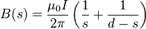 is small compared with the rail separation
and, by assuming that the railgun rails can be modelled as a pair of
semi-infinite conductors, we compute the following integral:
is small compared with the rail separation
and, by assuming that the railgun rails can be modelled as a pair of
semi-infinite conductors, we compute the following integral: , so since the width of the conductive projectile is , we have
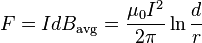
 ) between the point where the force (
 ) is measured and the beginning of the rails is greater than the separation of the rails () by a factor of about 3 or 4 (
 ).
Some other simplifying assumptions have also been made; to describe the
force more accurately, the geometry of the rails and the projectile
must be considered.
).
Some other simplifying assumptions have also been made; to describe the
force more accurately, the geometry of the rails and the projectile
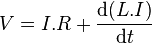
must be considered.Since it is not easy to produce an electromagnetic expression for the railgun force that is both simple and reasonably accurate, most simple railgun analyses actually used a lumped circuit model to describe the relationship between the driving current and the railgun force. In these models the voltage across the railgun breech is given by:


 which represents the electromagnetic work done. In this simple model,
exactly half of this is assumed to be needed to establish the magnetic
field along the barrel, i.e. as the length of the current loop
increases. The other half represents the power flow into the kinetic
energy of the projectile. Since power can be expressed as force times
speed, this gives the standard result that the force on the railgun
armature is given by:
which represents the electromagnetic work done. In this simple model,
exactly half of this is assumed to be needed to establish the magnetic
field along the barrel, i.e. as the length of the current loop
increases. The other half represents the power flow into the kinetic
energy of the projectile. Since power can be expressed as force times
speed, this gives the standard result that the force on the railgun
armature is given by:
This simple equation shows that high accelerations will require very high currents. For an ideal square bore railgun, the value of
 would be about 0.6 microHenries per metre (
 .H/m) but most practical railgun barrels exhibit lower values of than this.
Since the lumped circuit model describes the railgun force in terms of fairly normal circuit equations, it becomes possible to specify a simple time domain model of a railgun.
Ignoring friction and air drag, the projectile acceleration is given by:


Considerations
The power supply must be able to deliver large currents, sustained and controlled over a useful amount of time. The most important gauge of power supply effectiveness is the energy it can deliver. As of December 2010, the greatest known energy used to propel a projectile from a railgun was 33 megajoules.[10] The most common forms of power supplies used in railguns are capacitors and compulsators which are slowly charged from other continuous energy sources.The rails need to withstand enormous repulsive forces during shooting, and these forces will tend to push them apart and away from the projectile. As rail/projectile clearances increase, arcing develops, which causes rapid vaporization and extensive damage to the rail surfaces and the insulator surfaces. This limited some early research railguns to one shot per service interval.
The inductance and resistance of the rails and power supply limit the efficiency of a railgun design. Currently different rail shapes and railgun configurations are being tested, most notably by the United States Navy, the Institute for Advanced Technology, and BAE Systems.
Materials used
The rails and projectiles must be built from strong conductive materials; the rails need to survive the violence of an accelerating projectile, and heating due to the large currents and friction involved. Some erroneous work has suggested that the recoil force in railguns can be redirected or eliminated; careful theoretical and experimental analysis reveals that the recoil force acts on the breach closure just as in a chemical firearm.[11][12][13][14] The rails also repel themselves via a sideways force caused by the rails being pushed by the magnetic field, just as the projectile is. The rails need to survive this without bending and must be very securely mounted.Heat dissipation
Massive amounts of heat are created by the electricity flowing through the rails, as well as by the friction of the projectile leaving the device. The heat created by this friction itself can cause thermal expansion of the rails and projectile, further increasing the frictional heat. This causes three main problems: melting of equipment, decreased safety of personnel, and detection by enemy forces. As briefly discussed above, the stresses involved in firing this sort of device require an extremely heat-resistant material. Otherwise the rails, barrel, and all equipment attached would melt or be irreparably damaged.In practice the rails are, with most designs of railgun, subject to erosion due to each launch; in addition, projectiles can be subject to some degree of ablation, and this can limit railgun life, in some cases severely.[15]
Applications
Railguns have a number of potential practical applications, primarily for the military. However, there are other theoretical applications currently being researched.Launch or launch assist of spacecraft
Main article: Mass driver
See also: Space gun
Electrodynamic assistance to launch rockets has been studied.[16] Space applications of this technology would likely involve specially formed electromagnetic coils and superconducting magnets.[17] Composite materials would likely be used for this application.[18]For space launches from Earth, relatively short acceleration distances (less than a few km) would require very strong acceleration forces, higher than humans can tolerate. Other designs include a longer helical (spiral) track, or a large ring design whereby a space vehicle would circle the ring numerous times, gradually gaining speed, before being released into a launch corridor leading skyward.
| Key Parameters[19] | Value | Units |
|---|---|---|
| Muzzle Velocity | 7500 | m/s |
| Muzzle Energy | 35 | GJ |
| Launcher length | 1600 | m |
| Maximum acceleration | 19500 | m/s^2 |
| Maximum acceleration | 1988 | g's |
| Launch time | 0.43 | s |
| Current density | 6.8 | MA/m |
Weaponry

The increased launch velocities of railguns would also allow greater capability for both offensive and defensive applications as compared to traditional weapons. The greater kinetic energy and decreased time on target associated with increased launch velocities, when coupled with non-traditional rounds, would allow a single railgun to effectively attack both airborne and land or sea based targets.
If it were possible to apply the technology as a rapid-fire automatic weapon, a railgun would have further advantages of increased rate of fire. The feed mechanisms of a conventional firearm must move to accommodate the propellant charge as well as the ammunition round, while a railgun would only need to accommodate the projectile. Furthermore, a railgun would not have to extract a spent cartridge case from the breech, meaning that a fresh round could be cycled almost immediately after the previous round has been shot.
Many critics of weaponized railgun systems claim running at a suitable exit velocity and rate of fire would consume too much power, though this would likely not be a problem for nuclear-powered systems such as on large warships or submarines.
The first weaponized railgun planned for production, the General Atomics Blitzer system, began full system testing in September 2010. The weapon launches a streamlined discarding sabot round designed by Boeing's Phantom Works at 1,600 m/s (5,200 ft/s) (approximately Mach 5) with accelerations exceeding 60,000 g.[21] During one of the tests, the projectile was able to travel an additional 7 kilometres (4.3 mi) downrange after penetrating a 1⁄8 inch (3.2 mm) thick steel plate. The company hopes to have an integrated demo of the system by 2016 followed by production by 2019, pending funding. Thus far, the project is self-funded.[22]
In October 2013, General Atomics unveiled a land based version of the Blitzer railgun. A company official claimed the gun could be ready for production in "two to three years".[23]
The U.S. Navy plans to integrate a railgun that has a range of 100 mi (160 km) onto a ship by 2016.[24] By that time the Navy expects to have a weapon that can fire multiple projectiles per minute. The hyper-velocity rounds weigh 23 lb (10 kg) and cost about $25,000 each. They have command guidance but are planned to be self-guided in the future.[25] Currently the only ships that can produce enough electrical power to get desired performance are the Zumwalt-class destroyers; they can generate 78 megawatts of power, far more than would be necessary. Engineers are working to derive technologies from the DDG-1000 series ships into a battery system to store enough energy so other warships can operate a railgun.[26] Even if current ships, such as the Arleigh Burke-class destroyer, can be upgraded with enough power to operate a railgun, the space taken up on the ships by the integration of an additional weapon system may force the removal of existing weapon systems to make room available.[27] The first shipboard tests will be from a railgun installed on a Joint High Speed Vessel. Though ships of that class are non-combatants, they were chosen for their available cargo and topside space and schedule flexibility. They will not be permanently installed on the JHSV and the Navy has yet to decide which ship classes will receive a fully-operational railgun.[28]
Tests

The Yugoslavian Military Technology Institute developed, within a project named EDO-0, a railgun with 7 kJ kinetic energy, in 1985. In 1987 a successor was created, project EDO-1, that used projectile with a mass of 0.7 kg (1.5 lb) and achieved speeds of 3,000 m/s (9,800 ft/s), and with a mass of 1.1 kg (2.4 lb) reached speeds of 2,400 m/s (7,900 ft/s). It used a track length of 0.7 m (2.3 ft). According to those working on it, with other modifications it was able to achieve a speed of 4,500 m/s (14,800 ft/s). The aim was to achieve projectile speed of 7,000 m/s (23,000 ft/s). At the time, it was considered a military secret.[citation needed]
The United States military is funding railgun experiments. At the University of Texas at Austin Centre for Electromechanics, military railguns capable of delivering tungsten armor piercing bullets with kinetic energies of nine megajoules have been developed.[29] 9 MJ is enough energy to deliver 2 kg (4.4 lb) of projectile at 3 km/s (1.9 mi/s) – at that velocity a rod of tungsten or another dense metal could easily penetrate a tank, and potentially pass through it.
The United States Naval Surface Warfare Center Dahlgren Division demonstrated an 8 MJ railgun firing 3.2 kg (7.1 lb) projectiles in October 2006 as a prototype of a 64 MJ weapon to be deployed aboard Navy warships. The main problem the U.S. Navy has had with implementing a railgun cannon system is that the guns wear out due to the immense heat produced by firing. Such weapons are expected to be powerful enough to do a little more damage than a BGM-109 Tomahawk missile at a fraction of the projectile cost.[30] Since then, BAE Systems has delivered a 32 MJ prototype to the U.S. Navy.[31]
On January 31, 2008 the US Navy tested a railgun that fired a shell at 10.64 MJ with a muzzle velocity of 2,520 m/s (8,270 ft/s).[32] Its expected performance is a muzzle velocity over 5,800 m/s (19,000 ft/s), accurate enough to hit a 5-metre (16 ft) target over 200 nmi (370 km) away while firing at 10 shots per minute. The power was provided by a new 9-megajoule prototype capacitor bank using solid-state switches and high-energy-density capacitors delivered in 2007 and an older 32-MJ pulse power system from the US Army’s Green Farm Electric Gun Research and Development Facility developed in the late 1980s that was previously refurbished by General Atomics Electromagnetic Systems (EMS) Division.[33] It is expected to be ready between 2020 to 2025.[34]
A test of a railgun took place on December 10, 2010, by the US Navy at the Naval Surface Warfare Center Dahlgren Division.[35] During the test, the Office of Naval Research set a world record by conducting a 33 MJ shot from the railgun, which was built by BAE Systems.[36][37]
A more recent test took place in February, 2012, at the Naval Surface Warfare Center Dahlgren Division. While similar in energy to the aforementioned test, the railgun used is considerably more compact, with a more conventional looking barrel.[38] A General Atomics-built prototype was delivered for testing in October 2012.[39]
Trigger for inertial confinement fusion
Railguns may also be miniaturized for inertial confinement nuclear fusion.- Fusion is triggered by very high temperature and pressure at the core.
- Current technology calls for multiple lasers, usually over 100, to concurrently strike a fuel pellet, creating a symmetrical compressive pressure.
- Railguns may be able to trigger fusion by firing energetic plasma
from multiple directions. The process developed involves four key steps.[40]
- Plasma is pumped into a chamber.
- When the pressure is great enough, a diaphragm will rupture, sending gas down the rail.
- Shortly afterwards, a sufficient voltage is applied to the rails, creating a conduction path of ionized gas.
- This plasma accelerated down the rail, eventually being ejected at a large velocity.
- The rails and dimensions are on the order of centimetres.
No comments:
Post a Comment