From Wikipedia, the free encyclopedia

Gyroscopes based on other operating principles also exist, such as the electronic, microchip-packaged MEMS gyroscope devices found in consumer electronic devices, solid-state ring lasers, fibre optic gyroscopes, and the extremely sensitive quantum gyroscope.
Applications of gyroscopes include inertial navigation systems where magnetic compasses would not work (as in the Hubble telescope) or would not be precise enough (as in ICBMs), or for the stabilization of flying vehicles like radio-controlled helicopters or unmanned aerial vehicles. Due to their precision, gyroscopes are also used in gyrotheodolites to maintain direction in tunnel mining.[2]
Contents
Description and diagram

The outer gimbal or ring, which is the gyroscope frame, is mounted so as to pivot about an axis in its own plane determined by the support. This outer gimbal possesses one degree of rotational freedom and its axis possesses none. The next inner gimbal is mounted in the gyroscope frame (outer gimbal) so as to pivot about an axis in its own plane that is always perpendicular to the pivotal axis of the gyroscope frame (outer gimbal). This inner gimbal has two degrees of rotational freedom.
The axle of the spinning wheel defines the spin axis. The rotor is journaled to spin about an axis, which is always perpendicular to the axis of the inner gimbal. So the rotor possesses three degrees of rotational freedom and its axis possesses two. The wheel responds to a force applied about the input axis by a reaction force about the output axis.
The behaviour of a gyroscope can be most easily appreciated by consideration of the front wheel of a bicycle. If the wheel is leaned away from the vertical so that the top of the wheel moves to the left, the forward rim of the wheel also turns to the left. In other words, rotation on one axis of the turning wheel produces rotation of the third axis.
A gyroscope flywheel will roll or resist about the output axis depending upon whether the output gimbals are of a free- or fixed- configuration. Examples of some free-output-gimbal devices would be the attitude reference gyroscopes used to sense or measure the pitch, roll and yaw attitude angles in a spacecraft or aircraft.

In some special cases, the outer gimbal (or its equivalent) may be omitted so that the rotor has only two degrees of freedom. In other cases, the centre of gravity of the rotor may be offset from the axis of oscillation, and, thus, the centre of gravity of the rotor and the centre of suspension of the rotor may not coincide.
History

The first known use of such a top as an instrument came in 1743, when John Serson invented the "Whirling speculum" (or Serson's Speculum), a spinning top that was used as a level, to locate the horizon in foggy or misty conditions.
The instrument used more like an actual gyroscope was made by German Johann Bohnenberger, who first wrote about it in 1817. At first he called it the "Machine".[4][5] Bohnenberger's machine was based on a rotating massive sphere.[6] In 1832, American Walter R. Johnson developed a similar device that was based on a rotating disc.[7][8] The French mathematician Pierre-Simon Laplace, working at the École Polytechnique in Paris, recommended the machine for use as a teaching aid, and thus it came to the attention of Léon Foucault.[9] In 1852, Foucault used it in an experiment involving the rotation of the Earth.[10][11] It was Foucault who gave the device its modern name, in an experiment to see (Greek skopeein, to see) the Earth's rotation (Greek gyros, circle or rotation),[12] which was visible in the 8 to 10 minutes before friction slowed the spinning rotor.
In the 1860s, the advent of electric motors made it possible for a gyroscope to spin indefinitely; this led to the first prototype heading indicators and, quite more complicated devices, first gyrocompasses. The first functional gyrocompass was patented in 1904 by German inventor Hermann Anschütz-Kaempfe.[13] The American Elmer Sperry followed with his own design later that year, and other nations soon realized the military importance of the invention—in an age in which naval prowess was the most significant measure of military power—and created their own gyroscope industries. The Sperry Gyroscope Company quickly expanded to provide aircraft and naval stabilizers as well, and other gyroscope developers followed suit.[14]
In 1917, the Chandler Company of Indianapolis, created the "Chandler gyroscope", a toy gyroscope with a pull string and pedestal. Chandler continued to produce the toy until the company was purchased by TEDCO inc. in 1982. The chandler toy is still produced by TEDCO today.[15]
In the first several decades of the 20th century, other inventors attempted (unsuccessfully) to use gyroscopes as the basis for early black box navigational systems by creating a stable platform from which accurate acceleration measurements could be performed (in order to bypass the need for star sightings to calculate position). Similar principles were later employed in the development of inertial guidance systems for ballistic missiles.[16]
During World War II, the gyroscope became the prime component for aircraft and anti-aircraft gun sights.[17] After the war, the race to miniaturize gyroscopes for guided missiles and weapons navigation systems resulted in the development and manufacturing of so-called midget gyroscopes that weighed less than 3 ounces (85 g) and had a diameter of approximately 1 inch (2.5 cm). Some of these miniaturize gyroscopes could reach a speed of 24,000 revolutions per minute in less than 10 seconds.[18]
3-axis MEMS-based gyroscopes are also being used in portable electronic devices such as Apple's current generation of iPad, iPhone and iPod touch.[19] This adds to the 3-axis acceleration sensing ability available on previous generations of devices. Together these sensors provide 6 component motion sensing; acceleration for X,Y, and Z movement, and gyroscopes for measuring the extent and rate of rotation in space (roll, pitch and yaw).
Properties

The fundamental equation describing the behavior of the gyroscope is:
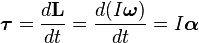
It follows from this that a torque τ applied perpendicular to the axis of rotation, and therefore perpendicular to L, results in a rotation about an axis perpendicular to both τ and L. This motion is called precession. The angular velocity of precession ΩP is given by the cross product:
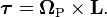

Under a constant torque of magnitude τ, the gyroscope's speed of precession ΩP is inversely proportional to L, the magnitude of its angular momentum:

By convention, these three vectors - torque, spin, and precession - are all oriented with respect to each other according to the right-hand rule.
To easily ascertain the direction of gyro effect, simply remember that a rolling wheel tends, when it leans to the side, to turn in the direction of the lean.
Variations
Gyrostat
A gyrostat is a variant of the gyroscope. It consists of a massive flywheel concealed in a solid casing.[20][21] Its behaviour on a table, or with various modes of suspension or support, serves to illustrate the curious reversal of the ordinary laws of static equilibrium due to the gyrostatic behaviour of the interior invisible flywheel when rotated rapidly. The first gyrostat was designed by Lord Kelvin to illustrate the more complicated state of motion of a spinning body when free to wander about on a horizontal plane, like a top spun on the pavement, or a hoop or bicycle on the road. Kelvin also made use of gyrostats to develop mechanical theories of the elasticity of matter and of the ether;[22] these theories are of purely historical interest today.In modern times, the gyrostat concept is used in the design of attitude control systems for orbiting spacecraft and satellites.[23] For instance, the Mir space station had three pairs of internally mounted flywheels known as gyrodynes or control moment gyros.
In physics, there are several systems whose dynamical equations resemble the equations of motion of a gyrostat.[24] Examples include a solid body with a cavity filled with an inviscid, incompressible, homogeneous liquid,[25] the static equilibrium configuration of a stressed elastic rod in elastica theory,[26] the polarization dynamics of a light pulse propagating through a nonlinear medium,[27] the Lorenz system in chaos theory,[28] and the motion of an ion in a Penning trap mass spectrometer.[29]
MEMS
A MEMS gyroscope takes the idea of the Foucault pendulum and uses a vibrating element, known as a MEMS (Micro Electro-Mechanical System). The MEMS-based gyro was initially made practical and producible by Systron Donner Inertial (SDI). Today, SDI is a large manufacturer of MEMS gyroscopes.FOG
A fiber optic gyroscope (FOG) is a gyroscope that uses the interference of light to detect mechanical rotation. The sensor is a coil of as much as 5 km of optical fiber. The development of low-loss single-mode optical fiber in the early 1970s for the telecommunications industry enabled the development of Sagnac effect fiber optic gyros.VSG or CVG
A vibrating structure gyroscope (VSG), also called a Coriolis Vibratory Gyroscope (CVG),[30] uses a resonator made of different metallic alloys. It takes a position between the low-accuracy, low-cost MEMS gyroscope and the higher-accuracy and higher-cost FOG. Accuracy parameters are increased by using low-intrinsic damping materials, resonator vacuumization, and digital electronics to reduce temperature dependent drift and instability of control signals.[31]High-Q Wine-Glass Resonators for precise sensors like HRG [32] or CRG [33]
DTG
A dynamically tuned gyroscope (DTG) is a rotor suspended by a universal joint with flexure pivots.[34] The flexure spring stiffness is independent of spin rate. However, the dynamic inertia (from the gyroscopic reaction effect) from the gimbal provides negative spring stiffness proportional to the square of the spin speed (Howe and Savet, 1964; Lawrence, 1998). Therefore, at a particular speed, called the tuning speed, the two moments cancel each other, freeing the rotor from torque, a necessary condition for an ideal gyroscope.London moment
A London moment gyroscope relies on the quantum-mechanical phenomenon, whereby a spinning superconductor generates a magnetic field whose axis lines up exactly with the spin axis of the gyroscopic rotor. A magnetometer determines the orientation of the generated field, which is interpolated to determine the axis of rotation. Gyroscopes of this type can be extremely accurate and stable. For example, those used in the Gravity Probe B experiment measured changes in gyroscope spin axis orientation to better than 0.5 milliarcseconds (1.4×10⁻⁷ degrees) over a one-year period.[35] This is equivalent to an angular separation the width of a human hair viewed from 32 kilometers (20 mi) away.[36]The GP-B gyro consists of a nearly-perfect spherical rotating mass made of fused quartz, which provides a dielectric support for a thin layer of niobium superconducting material. To eliminate friction found in conventional bearings, the rotor assembly is centered by the electric field from six electrodes. After the initial spin-up by a jet of helium which brings the rotor to 4,000 RPM, the polished gyroscope housing is evacuated to an ultra-high vacuum to further reduce drag on the rotor. Provided the suspension electronics remain powered, the extreme rotational symmetry, lack of friction, and low drag will allow the angular momentum of the rotor to keep it spinning for about 15,000 years.[37]
A sensitive DC SQUID magnetometer able to discriminate changes as small as one quantum, or about 2 ×10⁻¹⁵ Wb, is used to monitor the gyroscope. A precession, or tilt, in the orientation of the rotor causes the London moment magnetic field to shift relative to the housing. The moving field passes through a superconducting pickup loop fixed to the housing, inducing a small electric current. The current produces a voltage across a shunt resistance, which is resolved to spherical coordinates by a microprocessor. The system is designed to minimize Lorentz torque on the rotor.[38]
Modern uses
Gyroscope tops are sold as a common toy.
Main article: Accelerometer#Consumer_electronics
In addition to being used in compasses, aircraft, computer pointing
devices, etc., gyroscopes have been introduced into consumer
electronics. Since the gyroscope allows the calculation of orientation
and rotation, designers have incorporated them into modern technology.
The integration of the gyroscope has allowed for more accurate
recognition of movement within a 3D space than the previous lone
accelerometer within a number of smartphones. Gyroscopes in consumer
electronics are frequently combined with accelerometers (acceleration sensors) for more robust direction- and motion-sensing.Examples of Gyroscope in consumer electronics include HTC Titan,[39] Nexus 4, iPhone 4,[40] Nokia 808 PureView,[41] PlayStation 3 controller, Wii Remote,Sony Xperia etc.
Nintendo has integrated a gyroscope into the Wii console's Wii Remote controller by an additional piece of hardware called "Wii MotionPlus".[42] It is also included in the 3DS, which detects movement when turning.
Cruise ships use gyroscopes to level motion-sensitive devices such as self-leveling pool tables.
Described as a "motorbike-car" hybrid, the Lit Motors C-1 two wheeler uses a set of futuristic electronic gyroscopes, or Control Moment Gyroscope to ensure it remains upright and balanced, similar to the positioning technology used in the International Space Station and the Hubble Space Telescope. The only similarities the Lit C-1 shares with the Segway is an IMU. A similar device has been used in the RYNO and Honda UX3 monocycles.
An electric powered flywheel gyroscope inserted in a bicycle wheel is being sold as a training wheel replacement.
See also
- Aerotrim
- Anti-rolling gyro — Ship gyroscopic roll stabilizers.
- Attitude indicator
- Balancing machine
- Bicycle and motorcycle dynamics
- Countersteering
- Euler angles
- Eric Laithwaite
- Gyro monorail
- Gyrocar
- Gyrotheodolite
- Gyroscopic exercise tool
- Heading indicator
- Reaction wheel
- Rifling
- Rigid body dynamics
- Top
- Turn and bank indicator
- Turn coordinator
- LN-3 Inertial Navigation System
- Stabilizer (ship)
- Vibrating structure gyroscope
No comments:
Post a Comment