From Wikipedia, the free encyclopedia
Both the Allies and Axis powers used radar in World War II, and many important aspects of this conflict were greatly influenced by this revolutionary new technology.[1]
The basic technology of radio-based detection and tracking evolved independently and with great secrecy in a number of nations during the second half of the 1930s.[2] At the start of the war in Europe in September 1939, both Great Britain and Germany had begun the deployment of these systems. In Great Britain this technology was called RDF, standing for Range and Direction Finding, while in Germany the name Funkmessgerät (radio measuring device) was often used.
By the time of the Battle of Britain in mid-1940, the Royal Air Force (RAF) had incorporated RDF stations as vital elements in Britain's air-defence capabilities. The German Funkmessgerät, could not assist in Germany's offensive capability and was thus not supported by Adolf Hitler. Also, the Luftwaffe (German Air Force) did not sufficiently appreciate the importance of RDF stations in air defence, contributing to Germany's lack of success in this early stage of the war.
Although the technology was first demonstrated in the United States during December 1934,[3] it was only when war clouds loomed that the U.S. military authorities recognized the great potential of radio-based detection and tracking, and began the development of ship- and land-based systems. The first of these were fielded by the U.S. Navy in early 1940, and a year later by the U.S. Army. The acronym RADAR (for RAdio Detection And Ranging) was coined by the U.S. Navy in 1940, and the subsequent name "radar" was soon widely used.
While the great benefits of operating in the microwave portion of the radio spectrum were known, transmitters for generating microwave signals of sufficient power were not available; thus, all early radar systems operated at much lower frequencies. In February 1940, researchers in Great Britain developed the resonant-cavity magnetron, capable of producing microwave power in the kilowatt range, opening the path to second-generation radar systems.[4]
As the conflict in Europe got underway, it was realised in Great Britain that the development and manufacturing capabilities of the United States were vital to success in the war; thus, although America was not yet a direct participant in the war, Prime Minister Winston Churchill directed that the technology secrets of Great Britain be shared with this nation in exchange for the needed capabilities. In the summer of 1940, the Tizard Mission brought these secrets to the United States. The cavity magnetron was included, and almost immediately the Radiation Laboratory was established to develop microwave radars using the magnetron.[5]
In addition to Great Britain, Germany, and the United States, wartime radars were also developed and used by the Soviet Union and Japan, as well as the technically advanced Commonwealth Nations Australia, Canada, New Zealand, and South Africa. These developments and the resulting systems are also described herein. The Wikipedia article History of Radar provides a summary of pre-war developments in all of these countries as well as early activities in the Netherlands, France, Italy, and Hungary.

 Bawdsey Manor
In March 1936, the RDF research and development effort was moved to the Bawdsey Research Station located at Bawdsey Manor in Suffolk. While this operation was under the Air Ministry, both the Army and Navy became involved and soon initiated their own programs.
Bawdsey Manor
In March 1936, the RDF research and development effort was moved to the Bawdsey Research Station located at Bawdsey Manor in Suffolk. While this operation was under the Air Ministry, both the Army and Navy became involved and soon initiated their own programs.
At Bawdsey, outstanding engineers and scientists evolved the RDF technology, but much of the credit belongs to Watson-Watt, the head of the team, who turned from the technical side to building up a usable network of machines and the people to run them. After watching a demonstration in which his equipment operators were attempting to locate an "attacking" bomber, he noticed that the primary problem was not technological, but worker overload. Following Watson-Watt's advice, by early 1940 the RAF had built up a layered control organization that efficiently passed information along the chain of command, and was able to track large numbers of aircraft and direct defences to them.[6]
Immediately after the war began in September 1939, the Air Ministry RDF development at Bawdsey was temporarily relocated to University College, Dundee in Scotland. A year later, the operation moved to near Worth Matravers in Dorset on the southern coast of England, and was named the Telecommunications Research Establishment (TRE). In a final wartime move, the TRE relocated to Malvern College in Great Malvern, near Birmingham.
Some of the major RDF/radar equipment used by the Air Ministry is briefly described. All of the systems were given the official designation Air Ministry Experimental Station (AMES) plus a Type number; most of these are listed in this link.

Chain Home tower at Great Baddow
Shortly before the outbreak of World War II, several RDF (radar) stations known as Chain Home (or CH)
were constructed along the South and East coasts of Britain, based on
the successful model at Bawdsey. As one might expect from the first
equipment to be deployed, CH was a simple system. The broadcast side was
formed from two 300-ft (90-m) tall steel towers strung with a series of
antennas between them. A second set of 240-ft (73-m) tall wooden towers
were used for reception, with a series of crossed antennas at various
heights up to 215 ft (65 m). Most stations had more than one set of each
antenna, tuned to operate at different frequencies.
Typical CH operating conditions were:
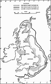
Chain Home coverage
CH proved highly effective during the Battle of Britain, and is often credited with enabling the RAF to defeat the much larger Luftwaffe forces. Whereas the Luftwaffe
had to hunt all over to find the RAF fighters, the RAF knew exactly
where the German bombers were, and could converge all of their fighters
on them. In modern terminology, CH was a force multiplier,
allowing the RAF fighters to operate more effectively as if they were a
much larger force operating at the same effectiveness as the Germans.
In addition, the CH system allowed pilots to rest on the ground instead
of flying continuous "standing patrols", and only needing to "scramble"
(take off) when the air threat was imminent. This not only reduced
pilots' workloads, but also reduced wear on engines, as well as reducing
unnecessary petrol consumption.
Very early in the battle the Luftwaffe made a series of small raids on a few of the stations, including the Bawdsey research and training station, but they were returned to operation in a few days. In the meantime the operators took to broadcasting radar-like signals from other systems in order to fool the Germans into believing that the systems were still operating. Eventually the Germans gave up trying to bomb them. The German High Command apparently never understood the importance of radar to the RAF's efforts, or they would have assigned these stations a much higher priority – even a concerted effort would not have had much effect on the transmitters as their structure made them very resistant to blast, which passed through the spaces in the metal lattice.
To avoid the CH system, the Luftwaffe adopted other tactics.
One was to approach Britain at very low levels, below the sight line of
the CH stations. This was countered to some degree with a series of
shorter range stations built right on the coast, known as Chain Home Low (CHL).
These systems had originally been intended to use for naval gun-laying
and known as Coastal Defence (CD), but their narrow beams also meant
they could sweep an area much closer to the ground without seeing the
reflection of the ground (or water) – known as clutter.
Unlike the larger CH systems, CHL had to have the broadcast antenna
itself turned, as opposed to just the receiver. This was done manually
on a pedal-crank system run by Women's Auxiliary Air Force until more reliable motorized movements were installed in 1941.

Battle of Britain defences of the UK
Systems similar to CH were later adapted with a new display to produce the Ground-Controlled Intercept (GCI)
stations in January 1941. In these systems the antenna was rotated
mechanically, followed by the display on the operator's console. That
is, instead of a single line across the bottom of the display from left
to right, the line was rotated around the screen at the same speed as
the antenna was turning.
The result was a 2-D display of the air space around the station with the operator in the middle, with all the aircraft appearing as dots in the proper location in space. Called plan position indicators (PPI), these dramatically simplified the amount of work needed to track a target on the operator's part. Such a system with a rotating, or sweeping, line is what most people continue to associate with a radar display. Philo Taylor Farnsworth, the American inventor of all-electronic television in 1927, contributed to this in an important way. Farnsworth refined a version of his picture tube (cathode ray tube, or CRT) and called it an "Iatron". It could store an image for milliseconds to minutes (even hours). One version that kept an image alive about a second before fading, proved to be a useful addition to the evolution of radar. This slow-to-fade display tube was used by air traffic controllers from the very beginning of radar.
This eventuality had already been foreseen, and a successful programme by Edward George Bowen starting in 1936 (likely at the urging of Tizard) developed a miniaturized RDF system suitable for aircraft, the Air Interception (AI) set. (Watson-Watt called the CH sets the RDF-1 and the AI the RDF-2A.) At the same time Bowen developed AI sets for aircraft to detect submarines, the Air to Surface Vessel (ASV) set was also developed, making a significant contribution to the defeat of the German U-boats.
Initial AI sets were available in 1939 and fitted to Bristol Blenheim aircraft, replaced quickly with the better-performing Bristol Beaufighter. These quickly put an end to German night- and bad-weather bombing over Britain. Later in the war, Mosquito night intruders were fitted with AI Mk VIII and later derivatives, which, along with a device called "Serrate" to allow them to track down German night fighters from their Lichtenstein signal emissions, as well as a device named "Perfectos" that tracked German IFF, allowed the Mosquito to find and destroy German night fighters. As a countermeasure the German night fighters employed Naxos ZR signal detectors.
The cavity magnetron was perhaps the single most important invention in the history of radar and played a major part in the Allies' victory. In the Tizard Mission during September 1940, it was given free to the U.S., together with several other inventions such as jet technology, so that the British could use American R&D and production facilities. The British need to produce the magnetron in large quantities was great. Consequently, Edward George Bowen was sent as the RDF expert in the Tizard Mission to the U.S. This led to the creation of the Radiation Laboratory (Rad Lab) at MIT to further develop the device and its applications. Half of the radar deployed during World War II were designed at the Rad Lab, including over 100 different systems costing $1.5 billion.[7]
When the cavity magnetron was first developed, its use in microwave RDF sets was held up because the duplexers for VHF were destroyed by the new higher-powered transmitter. This critical problem was solved in early 1941 by the T-R switch developed at the Clarendon Laboratory of Oxford University, allowing a pulse transmitter and receiver to share the same antenna without destabilizing the sensitive receiver.
The combination of the magnetron, the T-R switch, small antennas and high resolution allowed small high quality radars to be installed in aircraft. They could be used by maritime patrol aircraft to detect objects as small as a submarine periscope, which allowed aircraft to attack and destroy submerged submarines, which had previously been undetectable from the air. Centimetric contour mapping radars like H2S, and the even higher frequency American-created H2X improved the accuracy of Allied bombers used in the strategic bombing campaign. Centimetric gun laying radars were much more accurate than the older technology. They made the big gunned Allied battleships more deadly and along with the newly developed proximity fuze made anti-aircraft guns much more dangerous to attacking aircraft. The two coupled together and used by anti-aircraft batteries, placed along on the German V-1 flying bomb flight paths to London, are credited with destroying many of the flying bombs before they reached their target.
When the war started and the Air Ministry activities were relocated to Dundee in Scotland, the Army Cell became a part of a new developmental center at Christchurch in Dorset on the south coast. John D. Cockcroft a physicist from Cambridge University and later a Nobel Prize Laureate, became the Director. With enlarged activities, the facility became the Air Defence Research and Development Establishment (ADRDE) in mid-1941. A year later, the ADRDE relocated to Great Malvern, in Worcestershire near Birmingham. In 1944, this was reorganized as the Radar Research and Development Establishment (RRDE).[9]
As the war started, GL Mk I sets were used overseas by the British Army in Malta and Egypt in 1939–40. Seventeen sets were sent to France with the British Expeditionary Force; most of these were destroyed at the Dunkirk evacuation in late May 1940, but a few were captured and gave the Germans their first full information on British RDF hardware. An improved version, GL Mk II, was used throughout the war; some 1,700 sets were put into service, including over 200 supplied to the Soviet Union. Operational research found that anti-aircraft batteries using the GL averaged 4,100 rounds fired per hit, compared with about 20,000 rounds for unassisted guns.
Early tests showed that the CD set had much better capabilities for detecting aircraft at low altitudes than the existing CH. Consequently, the CD was also adopted by the Air Defence to augment the CH stations; in this role it was designated the Chain Home Low (CHL).
A few representative radars are described. Note that the type numbers are not sequential by date.
The initial Type 271 primarily found service on smaller vessels. At ASE Witley, this set was modified to become Type 272 and Type 273 for larger vessels. With larger reflectors, the Type 273 also served well as air-warning against low-flying aircraft, with a range up to 30 miles. A close relative was the Type 277, a "nodding" 10-cm height-finding system. The "cheese-style" antenna was mounted vertically to generate a horizontally flattened beam. This was the first Royal Navy radar with a plan-position indicator. In addition to the microwave warning systems, Coales developed the Type 275 and Type 276 microwave fire-control sets. Further development in magnetrons resulted in 3.2-cm (9.4-GHz) devices generating 25-kW peak power. These were used in the Type 262 fire-control radar and Type 268 target-indication and navigation radar.
The Navy, however, did not follow this initial effort with a vigorous pursuit, and it was not until January 1939, that their first prototype system, the 200-MHz (1.5-m) XAF, was tested at sea. The Navy coined the acronym RAdio Detection And Ranging (RADAR) for this technology, and in late 1940, ordered this to be exclusively used in documents.
Taylor's 1930 report had been passed on to the U.S. Army's Signal Corps Laboratories (SCL). Here, William R. Blair had projects underway in detecting aircraft from thermal radiation and engine ignition noise, and soon started a project in Doppler-beat detection. Following the success by Page with pulse-transmission, the SCL soon had their own project in this area. In 1936, Paul E. Watson led in the development of a pulsed system that on December 14 detected aircraft flying in and out of New York City at ranges up to seven miles. By 1938, this had evolved into the Army's first Radio Position Finding (RPF) set, designated SCR-268 (SCR meaning Signal Corps Radio, a cover for this secret technology). It operated at 200 MHz 1.5 m, with 7-kW peak power. The received signal was used to direct a searchlight.
In Europe, the continued war with Germany had drained the United Kingdom of resources, and the decision was made by Prime Minister Winston Churchill to give UK's existing technology secrets to the United States in exchange for access to related American secrets and manufacturing capabilities. In September 1940, the Tizard Mission coordinated this exchange, including the cavity magnetron, Great Britain's greatest secret.
When the exchange began, the British were surprised to learn they were not unique in their possession of pulse-radar technology. The U.S. Navy's pulse radar system, the CXAM, was found to be very similar in capability to their Chain Home technology. Although the U.S. had developed pulsed radar independent of the British, there were serious weaknesses in America's efforts, the greatest of which was the lack of integration of radar into a unified air defense system. Here the British were without peer.
The result of the Tizard Mission was a major step forward for utilization of radar technology, both in the transfer of the organizational knowledge that Watson-Watt had worked out as well as the British microwave technology. Although both the NRL and SCL had experimented with 10–cm transmitters, they were stymied by the problem of insufficient transmitter power. The cavity magnetron was the answer the U.S. was looking for, and it led to the creation of the MIT Radiation Laboratory (Rad Lab). Before the end of 1940, the Rad Lab was started at MIT, and thereafter essentially all radar development in the U.S. was in centimeter-wavelength systems. This major center for research employed almost 4,000 people at its peak during World War II.
Two special radar-related organizations should be noted. As the Rad Lab began operations at MIT, a companion group called the Radio Research Laboratory (RRL) was established at nearby Harvard University. Headed by Frederick Terman, this was devoted to research and development in electronic countermeasures to radar. Another organization was the Combined Research Group (CRG) housed in highest secrecy at the NRL. This involved American, British, and Canadian personnel charged with developing standardized Identification Friend or Foe (IFF) systems used with radars, vital in preventing fratricide.
As previously described, the SCL's first radio-based detection and tracking system, designated SCR-268, was demonstrated in late 1938. Even before this went into service, Harold Zahl led a team at the SCL in developing a better system; the SCR-270 was the mobile version, and the SCR-271 a fixed-position version. Operating at 106 MHz (2.83 m) with 100 kW pulsed power, these had a range up to 240 miles and began entry into service in late 1940. On December 7, 1941, an SCR-270 at Oahu in Hawaii detected the attacking Japanese aircraft at a range of 132 miles (212 km), but this information was not used effectively at the command level.
Only one other metric radar of significance was developed by the SCL. After Pearl Harbor, there was concern that a similar attack might be used to destroy locks at the vital Panama Canal. A transmitter tube that delivered 240-kW pulsed power at 600 MHz (0.5 M) had been developed by Zahl. A team led by John W. Marchetti used this tube in adapting an SCR-268 suitable for picket ships operating up to 100 miles offshore. The same basic set was modified to become the AN/TPS-3, a light-weight, portable, early-warning radar used at beachheads and captured airfields in the South Pacific. About 900 of these radars were produced.[12]
A British ASV Mk II, was brought to America by the Tizard Mission. With the ASE for use on large patrol aircraft such as the PBY Catalina. This was America's first airborne radar in operational service; about 7,000 ASEs were built. The NRL was already working on a 515-MHz (58.3-cm) air-to-surface radar for the TBF Avenger, a new fighter-bomber. Portions of the ASE were adopted for this radar, and it went into production as the ASB when the U.S. entered the war. This set was also adopted by the newly formed Army Air Forces as the SCR-521. The last of the non-magnetron radars, over 26,000 ASB/SCR-521 sets were built.
The history of World War II radar could not be complete without noting the Variable Time (VT) Fuze. Although not a radar per se, it was closely associated with this technology and involved one of the largest financial outlays of World War II. In the summer of 1940, the National Defense Research Committee (NDRC), predecessor of the OSRD (noted later) asked Merle Tuve of the Carnegie Institution of Washington to take the lead in developing a device that could increase the probability of kill for gun projectiles. From this, the variable-time fuze emerged as an improvement for the fixed-time fuze commonly used to detonate the projectile. The resulting device sensed when the projectile neared the target – thus, the name variable-time was applied. Alan Butement had actually conceived the idea for a proximity fuse while he was developing the Coastal Defense system in Great Britain during 1939, and his basic concept had been brought to the U.S. by the Tizard Mission.
A VT fuze, screwed onto the head of a projectile, radiated a CW signal in the 180–220 MHz range. As the projectile neared its target, this was reflected at a Doppler shifted frequency by the target and beat with the original signal, the amplitude of which triggered the detonation. The device used electronics much smaller than anything previously built, and 112 industries and research institutions were eventually involved. In 1942, the project was transferred to the Applied Physics Laboratory, formed by Johns Hopkins University for this purpose. During the war, some 22 million VT fuses for several sizes of projectiles were manufactured.
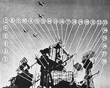
Radar arrangement on the aircraft carrier Lexington, 1944
In the period 1941–1945, many different radars operating in the
microwave region were developed in America. These mainly originated in
the Rad Lab where some 100 different types were initiated. Although many
industries manufactured sets (primarily for the Navy and Army Air
Forces), only Bell Telephone Laboratories (NTL) had major involvement in
development. The two primary military research operations, NRL and SCL,
had major efforts in component development, system engineering,
testing, and other support to the Rad Lab, but did not take on wartime
responsibilities for developing new centimeter radar systems.
Operating under the Office of Scientific Research and Development, an agency reporting directly to President Franklin Roosevelt, the Rad Lab was directed by Lee Alvin DuBridge with the eminent scientist Isidor Isaac Rabi serving as his deputy. E. G. "Taffy" Bowen, one of the original developers of RDF and a member of the Tizard Mission, remained in the U.S. as an adviser to the Rad Lab.
As it was formed, the Rad Lab was assigned three initial projects: a 10 cm airborne intercept radar, a 10 cm gun-laying system for anti-aircraft use, and a long-range aircraft navigation system. The cavity magnetron brought to America by the Tizard Mission was exactly duplicated by the Bell Telephone Laboratories (BTL) and placed into production for use by the Rad Lab in the first two projects. The third project, which did not involve radar, ultimately became LORAN, the first worldwide radio navigation system. LORAN was conceived by Alfred Lee Loomis, a financial tycoon and private scientist who was instrumental in starting the Rad Lab.[13]
To get underway, the Rad Lab built an experimental breadboard set with a 10 cm transmitter and receiver using separate antennas (the T-R switch was not yet available). This was successfully tested from atop the laboratory at MIT in February 1941, detecting an aircraft at a range of 4 miles.
The Rad Lab and BTL also initiated improvements in the magnetron, extending the device and associated systems to higher wavelengths. As more frequencies were used, it became common to refer to centimeter radar operations in the following bands:
A compact version of the SG for PT boats was designated the SO. These were introduced in 1942. Other direct descendants included the SF, a search-set for lighter warships, the SH for large merchant vessels, and the SE and SL, similar to the SO, for other smaller ships. The Navy also adopted versions of the Army's SCR-584 (without the M-9 unit but with gyro-stabilizers) for shipboard search radars, the SM for heavy carriers and the SP for smaller carriers. None of these were produced in large quantities, but were of great service in the war effort.
The BTL developed the SJ, an S-Band supplement for the SD meter-wave radar on submarines. The antenna for the SJ could be sweep the horizon to about 6 miles with good accuracy. Late in the war, the SV became available, increasing the detection range to 30 miles.
The Alvarez antenna was also used in developing the Ground Control Approach (GCA), a combined S-Band and X-Band blind-landing system for military airports; this system was particularly used in assisting planes returning from bombing runs.
The BTL also developed X-Band radars. The Mark 8 (FH) fire-control radar, was based on a new type of antenna developed by George Mueller. This was an end-fired array of 42 pipe-like waveguides that allowed electronic steering of the beam; for this the BTL developed the Mark 4 Fire Control Computer. The Mark 22 was a "nodding" system used for target height-finding with fire-control radars. With an antenna shaped like an orange slice, it gave a very narrow, horizontal beam to search the sky. The Army also adopted this as the AN/TPS-10, a land-version that was commonly called "Li'l Abner".
Although not implemented into a full system until after the war, the monopulse technique was first demonstrated at the NRL in 1943 on an existing X-Band set. The concept is attributed to Robert Page at the NRL, and was developed to improve the tracking accuracy of radars.[15] Following the war, essentially all new radar systems used this technology, and was the basis of the AN/FPS-16, the most widely used tracking radar in history.
The Soviet Union entered World War II with the Soviet invasion of Poland
in September 1939. Although the USSR had outstanding scientists and
engineers, began research on what would later become radar (radiolokatsiy)
as soon as anyone else, and made good progress with early magnetron
development, it entered the war without a fielded, fully capable radar
system.[16]
In only a few years after the close of World War I, Germany's Luftwaffe had aircraft capable of penetrating deep into Soviet territory. Visual observation was use for detecting approaching aircraft. For nighttime detection, the Glavnoe artilkeriisko upravlenie (GAU, Main Artillery Administration), of the Red Army, had developed an acoustical unit that was used to aim a searchlight at the aircraft. These techniques had a problem with aircraft that were above the clouds or at a considerable distance; to overcome this, research was also initiated on detection by electromagnetic means. General-leitenant (Lieutenant-General) M. M. Lobanov was responsible for these efforts in the GAU, and later thoroughly documented this activity.[17]
While the GAU was mainly interested in detection, the Voiska Protivo-vozdushnoi aborony (PVO, Air Defense Forces) was interested in also determining the distance to the aircraft (the range). Pavel K. Oshchepkov on the PVO technical staff in Moscow, strongly believed that the radiolokatory (radio-location) equipment should be pulsed, thus potentially allowing the range to be determined directly. He was transferred to Leningrad to be in charge of a Special Construction Bureau (SCB) for radio-location equipment.
To examine the various types of detection, a meeting was called by the Russian Academy of Sciences; this was held at Leningrad on January 16, 1934, and chaired by Ioffe. Radio-location emerged as the most promising technique, but the type (CW or pulsed) as well as the wavelength region (high frequency or microwave) were left to be resolved[18]
At the SCB, Oshchepkov's team developed an experimental pulsed radio-location system operating at 4 m (75 MHz.). This had a peak power of about 1 kW and a 10-μs pulse duration; separated transmitting and receiving antennas were used. In April 1937, test showed a detection range of near 17 km at a height of 1.5 km. Although this was a good beginning for pulsed radio-location, the system was not capable of directly measuring range (the technique of using the pulses for determining range was known from studies of the ionosphere but was not initially incorporated ). Although he never had the opportunity to add ranging to his system, Oshchepkov is nevertheless often called the father of radar in the Soviet Union.[19]

RUS–1. Receiver
While Oshchepkov was working on pulsed systems, work continued on CW
research at the LEPI. In 1935, the LEPI became a part of the Nauchno-issledovatel institut-9 (NII-9, Scientific Research Institute #9), one of several technical organizations under the GAU. With M. A. Bonch-Bruevich
as the Scientific Director, research continued in CW techniques.
Several experimental systems were developed, including a VHF set
designated Bistro (Rapid) and Burya (Storm) operating in the microwave region. The best elements of these were incorporated into a mobile system called Ulavlivatel Samoletov (Radio Catcher of Aircraft), soon designated as RUS-1 (РУС-1). This CW, bi-static system had a truck-mounted transmitter operating at 4.7 m (64 MHz) and two truck-mounted receivers.
In June 1937, all of the work in Leningrad on radio-location suddenly stopped. The infamous Great Purge of Joseph Stalin swept over the military high commands and the supporting scientific community, resulting in near two million executions.[20] The SCB was closed; Oshchepkov was charged with "high crimes" and sentenced to 10 years at a Gulag penal labor camp. The NII-9 was also intended to be closed, but was saved through the influence of Bonch-Bruyevich, who had been a favorite of Vladimir Lenin in the prior decade, NII-9 as an organization was saved, and Bonch-Bruyevich was named the new director. Overall, this resulted in a loss of more than a year in development activities.
The RUS-1 system was tested and put into production in 1939, then entered limited service in 1940, becoming the first deployed radio-location system in the Red Army. Bonch-Bruyevich died in March, 1941, and there was no strong leader to further push the CW radio-location developments.
The Nauchnoissledovatel skii ispytalel nyi institut suyazi RKKA (NIIIS-KA, Scientific Research Institute of Signals of the Red Army), an organization that had originally highly opposed radio-location technology, was now placed in overall control of this development in all of the Soviet Union. They took over Oshchepkov's pulsed system, and by July 1938, had a fixed-position, bistatic experimental system that detected an aircraft at 30-km range at heights of 500 m, and at 95-km range for high-flying targets at 7.5 km altitude.
The project was then taken up by Ioffe's LPTI, resulting in the development of a system designated Redut (Redoubt) with 50-kW peak-power and a 10-μs pulse-duration. The Redut was first field tested in October 1939, at a site near Sevastopol, a strategic port in Crimea on the coast of the Black Sea.

RUS–2. Receiver (artist's impression)
During 1940, the LEPI took over Redut and developed the very
important capability of range measurements. A cathode-ray display, made
from an oscilloscope, was used to show the range information. In July
1940, the resulting system was designated RUS-2 (РУС-2).
A transmit-receive device (a duplexer) to allow operating with a common
antenna was developed in February 1941. All of this testing was done at
an experimental station at Toksovo (near Leningrad), and an order was placed with the Svetlana Factory for 15 systems.
The final RUS-2 had pulse-power of near 40 kW at 4 m (75 MHz). The equipment was in a cabin on a motor-driven platform, and with a seven-element Yagi-Uda antenna mounted about five meters above the roof. The cabin, and thus the antenna, could be rotated over a large sector to aim the transmit-receive pattern. The detection range was 10 to 30 km for targets as low as 500 m and 25 to 100 km for higher-altitude targets. The variance was about 1.5 km for range and 7 degrees for azimuth.
At the LEMO, magnetrons were a major item of research. By 1934, a team led by Aleksandr Y. Usikov had developed a number of segmented-anode magnetrons covering 80 to 20 cm (0.37 to 1.5 GHz), with output power between 30 and 100 W. Semion Y. Braude developed a glass-cased magnetron producing up to 17 kW with 55 percent efficiency at 80 cm (370 kHz), tunable over a wavelength change of 30 percent. These were described in detail in German-language journal papers – a practice adopted by the UIPT to gain widespread readership of their work.
In 1937, the NIIIS-KA contracted with the LEMO for developing a pulsed radio-location system for anti-aircraft applications. The project was code-named Zenit (a popular football team at the time) and was under the guidance of Slutskin. The transmitter development was led by Usikov. The unit used a 60-cm (500-MHz) magnetron pulsed at 7–10-μs duration and providing 3-kW pulsed power, later increased to near 10 kW.[21]
Braude led the development of the receiver. This was a superheterodyne unit initially using a tunable magnetron as the local oscillator, but this lacked stability and was replaced with a circuit using an RCA type 955 acorn triode. The returned pulses were displayed on a cathode-ray oscilloscope, giving range measurement.
Zenit was first tested in October 1938. In this, a medium-sized bomber was detected at a range of 3 km, and needs for improvements were determined. After the changes had been made, a demonstration was given to all of the interested customers in September 1940. It was shown that the three coordinates (range, altitude, and azimuth) of an aircraft flying at heights between 4,000 and 7,000 meters could be determined at up to 25-km distance, but not with suitable accuracy. Also, with the antennas aimed at a low angle there was a dead zone of some distance; this was caused by interference from ground-level reflections.
While this performance was not satisfactory for immediate gun-laying applications, it did show the way for future systems. Another characteristic, however, rendered Zenit completely unsuitable for use with fire-controllers on anti-aircraft guns. A null-reading method was used for analyzing the signals; this made it necessary to determine azimuth and elevation coordinates independently, requiring a sequence of antenna movements that took 38 seconds for the three coordinates.
Work at the LEMO continued on Zenit, particularly in converting it into a single-antenna system designated Rubin. This effort, however, was disrupted by the invasion of the USSR by Germany in June 1941. In a short while, all of the critical industries and other operations in Kharkov were ordered to be evacuated far into the East.
A number of different radar systems were produced by the Soviet Union in the relocated facilities during the war. However, some 2,600 radar sets of various types were provided by Great Britain and America under the Lend-Lease Program.[22]
When air attacks on Leningrad began, the RUS-2 test unit that had been set up at the Toksovo experimental site was pressed into tactical operation, providing early-warning of Luftwaffe (German Air Force) raids that were often in formations of as many as 100 bombers. With a range up to 100 km, this unit gave a good warning to the city, as well as to notifying the defending fighter aircraft. This gained the attention of military leaders who previously had shown little interest in radio-location equipment.
In mid-July, the radio-location activities of the LEPI and NII-9 were sent to Moscow where they were combined with existing units of the NIIIS-KA. A RUS-2 system was set up near Moscow and manned by recently moved LPTI personnel; it was first used on July 22, when it detected at night an incoming flight of about 200 German bombers while they were 100 km away. This was the first air attack on Moscow, and it immediately led to three rings of anti-aircraft batteries being built around the city, all connected to a central command post.
Several transmitters and receivers built for RUS-2 systems were quickly adapted by the NIII-KA for fixed radio-location stations around Moscow. Designated as RUS-2S and also P2 Pegmatit, these had their Yagi antenna mounted on 20-meter steel towers and could scan a sector of 270 degrees. For building additional equipment, in January 1942, Factory 339 in Moscow became the first manufacturing facility in the Soviet Union devoted to radio-location sets (soon officially called radar). During 1942, this facility built and installed 53 RUS-2S sets around Moscow and other critical locations in the USSR.
Factory 339 had an outstanding research and engineering staff; this had earlier been administratively separated and designated as the Scientific Institute of Radio Industry No. 20 (NII-20). Victor V. Tikhomirov, a pioneer in domestic aircraft radio engineering, was the Technical Director. (Later, the Tikhomirov Scientific Research Institute of Instrument Design was named in his honor.) Factory 339 and the associated NII-20 dominated radar equipment development and fabrication in the USSR throughout the war.
Many sets of a number of different versions of the RUS-2 were built at Factory 339 during the war. While providing early warning, these sets suffered from the deficiency of not providing target height (elevation angle). Thus, they were mainly used in conjunction with visual-observation posts, with humans using optical devices for estimating altitude and identifying the type of aircraft.
From the time of the first efforts in radio-location, the question had been raised as to how the aircraft identification could be made – was it friendly or an enemy? With the introduction of RUS-2, this problem required an immediate solution. The NII-20 developed a unit to be carried on an aircraft that would automatically respond as "friendly" to a radio illumination from a Soviet radar. A transponder, designated as SCH-3 and later called an Identification Friend or Foe (IFF) unit, was placed into production at Factory 339 in 1943. This unit initially responded only to the signal of RUS-2, and only a relatively small number of these and successor units were built in the USSR.
The RUS-2 was sponsored by the PVO and intended for early warning. The GAU still wanted a gun-laying system capable of supporting the anti-aircraft batteries. Upon arriving in Moscow, the radio-location group of the NII-9 continued working for the PVO on this problem, returning to Burya, the experimental microwave set built earlier. Within a few weeks, a team led by Mikhail L. Sliozberg and with the cooperation of NII-20, developed a bi-static CW set designated Son (Sleep) using a 15-cm (2.0-GHz) magnetron.
In early October, the experimental Son set was tested in combat by an anti-aircraft battalion near Moscow. The performance of the radio-based Son was poor as compared with that of the existing optics-based Puazo-3, a stereoscopic range-finder that Oshchepkov had earlier improved. The project was discontinued, and no further attempts were made to use magnetrons in radio-location sets. After this failure, NII-9 was sent elsewhere and was no longer involved in radio-location activities. A portion of the radio-location group, including Sliozberg, remained in Moscow working for NII-20.
Shortly after Germany invaded the USSR, a delegation of Soviet military officers visited Great Britain seeking assistance in defense hardware. From their intelligence sources, the Soviets were aware of Britain's gun-laying RDF (Range and Direction Finding) system, the GL Mk II, and asked for this equipment to be tested in the defense of Moscow. In early January 1942, Winston Churchill agreed to send one of these systems to Russia, but with the provision that it would be totally secured under British officers and operated by British technicians.
When the ship carrying the equipment arrived at Murmansk, a seaport off the Bering Sea above the Arctic Circle, there was a winter storm and unloading had to wait overnight. The next morning, it was found that the entire GL Mk II system – mounted on three trucks – had disappeared. The British Embassy made an immediate protest, and after several days the officers were informed that the equipment had been taken to Moscow for security.
It indeed had gone to Moscow – directly to NII-20 and Factory 339, where intelligence experts gave it a total examination and Sliozberg led a team in quickly reverse-engineering the hardware. In mid-February, the NII-20 announced that it had developed a new radio-location system designated Son-2a. It was essentially a direct copy of the GL Mk II.
Operating at 5 m (60 MHz), Son-2a used separate trucks for the transmitting and receiving equipment, and a third truck carried a power generator. In use, a dipole-array transmitting antenna giving a broad pattern was fixed in position atop a grounded pole. Separated from the transmitter by about 100 meters, the receiving station was on a rotatable cabin with wing-like antennas mounted on each side. A mast above the cabin held a pair of antennas that were used with a goniometer for height-finding.
Like its GL Mk II "parent" in Great Britain, the Son-2a was not of great assistance in directing searchlights and anti-aircraft guns. Nevertheless, it was put into production and released to the Red Army in December 1942. Over the next three years, about 125 of these sets were built. In addition, over 200 GL Mk IIIC systems (improvements over the Mk II and built in Canada)[23] were provided under the Lend-Lease program, making the combination the most-used radar equipment in the Soviet Union during the war.
Ukraine had been the third objective of the invading German Army. By late July 1941, the mechanized forces were approaching this region, and, following orders from the Defense Committee, the UIPT in Kharkov made evacuation preparations. For this, the LEMO was split from the UIPT, and the two organizations would be sent to different cities: Alma-Ata for the main operation and, separated by 1,500 km, Bukhara for the LEMO.
While the preparations for moving were going on, the LEMO was directed to bring the experimental Zeni equipment to Moscow for testing by the NIIIS-KA. In mid-August, Usikov, Braude, and several other LEMO staff members went to Moscow, where they were attached to the NIIIS-KA. The Zenit system was installed in the Moscow outskirts, giving the opportunity for testing in combat. It was found that, while the accuracy of the system was not sufficient for precise aiming, it was satisfactory for barrage firing. It could also be used as a supplement to the RUS-2 surveillance system in guiding fighter aircraft.
In September, the team made field modifications to the Zenit and more tests were run. It was found that the detection range had been doubled, but the dead zone increased by a like amount. The NIIIS-KA believed that the prospects were good for this to be developed into a suitable system, but laboratory conditions were necessary. Thus, the Zenit and all of the NIIIS-KA staff were sent 3,200 km away to Bukhara, joining the remainder of the LEMO as it also moved.
Because of the null-reading method of analyzing the signals, the Zenit system suffered from slowness in measurements (38 seconds for determining the three coordinates) as well as accuracy. It also had a large dead zone caused by ground returns. While still at Kharkov, work had started on Rubin, a system intended to correct Zenit deficiencies. With Slutskin as LEMO Director, this project continued at Bukhara under Usikov's leadership.
A new magnetron was developed; this operated at 54 cm (470 MHz) with a pulse-power increased to 15 kW. A gas-discharge transmit-receive device (a diplexer) was developed for isolating the receiver from the direct transmitter pulse, thus allowing the use of a common transmitting-receiving structure. (A similar development had been made for the RUS-2 common antenna, but this would not have been suitable for the microwave Rubin.)
Several techniques for replacing the null-reading methods were considered, with the final selection making use of a fixture to provide a stationary dipole against which the directional position of the antenna could be continuously determined. Range, azimuth, and elevation were shown on a cathode-ray tube display. There was no provision, however, for feeding this information into an automatic unit for aiming searchlights and guns.
Separate transmitting and receiving dipoles were at the focus of a 3-meter paraboloid reflector. The antenna assembly, with remote controls, could rotate 0–90 degrees vertically and 0–400 degrees horizontally. The width of the main beam was 16 degrees equatorial and 24 degrees meridian.
The system was carried on two trucks, the electronics and control console in one and the power generator in the other. Both the transmitter magnetron and front-end portions of the receiver were in sealed containers attached to the rear of the reflector. The antenna assembly was on rails and could be rolled out to near the truck.
By August 1943, the prototype Rubin system was completed, with all of the work performed by the small LEMO and NIIIS-KA staffs. The system was transported to Moscow where Usikov, Truten, and others conducted further tests and gave non-combat demonstrations. By this time, the British GL Mk II and its Soviet replication, Sun-2a, were also available and were possibly used in direct comparison with the Rubin; if so, the Rubin would not have fared well.
Rather than releasing the prototype for production, the Army made arrangements for the Rubin to be tried by the Red Fleet Command. At the beginning of 1944, the system was transported to Murmansk, the only non-freezing port in the Soviet Arctic. Here, despite the cold, Usikov continued with tests and demonstrations under better conditions than in the still chaotic Moscow.
Test aboard a ship showed aircraft detection at 60 km and reliable measurement starting at 40 km. The mean errors were no more than 120-m in range and 0.8-degree in azimuth and elevation angles. The time for determining the angular coordinates never exceeded 7 seconds, and the dead zone was down to 500 m. Similar accuracies were found for detecting all types of surface vessels, but with the Rubin antenna at deck level, the detection range was understandably much less than that for aircraft.
During the last year of the war, Rubin was used by the Red Fleet for air and surface surveillance in the polar sector. If the GL Mk II and its clone, SUN-2a, had not become available, the Rubin would likely have been completed much earlier and gone into production. Although never put into regular service, this system provided a good foundation for future magnetron-based radars in the Soviet Union.
In late 1940, the VVS developed the requirement for an on-board enemy aircraft detection system. The radio-location group at NII-9 in Leningrad was directed to design such a set for the Pe-2. Most of radio-location equipment at that time was large and heavy, and for this aircraft, a small, lightweight set was needed. Also, limitations on antenna size drove the design to frequencies as high as possible. The reflex klystron (as it was later called) had just been developed by Nikolay Devyatkov. Using this, design was started on a set designated Gneis (Origin) and operating at 16 cm (1.8 GHz).
When the NII-9 was evacuated to Moscow in July 1941, this greatly affected the schedule. Also, the reflex klystron had not been put into production and its availability in the future was doubtful; therefore, the project was terminated. The need, however, for an airborne radio-location set was now even more important; the Pe-3, a heavy fighter aircraft and successor to the Pe-2, was in production. Some of these aircraft were being configured as night-fighters, and the radar (as it was now called) was urgently needed. The NII-20 and Factory 339 took up the design, led by the Technical Director, Victor Tikhomirov.
The new set, designated Gneis-2 (Гнейс-2), operated at 1.5 m (200 MHz). The Pe-3 fighter was a two-place aircraft, with the pilot and the rear gunner/radio operator seated back to back. The radar was designed as another piece of equipment for the radio operator.
The antennas were mounted above the top surface of the wings, a broad-pattern transmitting array on one wing and two Yagi receiving antennas on the other. One Yagi was directed forward and the other, a few feet away, aimed outward 45 degrees. The fuselage of the aircraft provided a shield between the transmitting and receiving antennas. The system had a range of about 4 km and could give the target's azimuth relative to the fighter's flight path.
The Gneis-2, the first aircraft radar in the Soviet Union, was proven in combat at Stalingrad during December 1942. About 230 of these sets were built during the war. A few were installed on Yak-9 and (out of number sequence) Yak-3 aircraft, the advanced fighters that eventually gave the VVS parity with the Luftwaffe. Other sets with Gneis designations were developed at Plant 339 for experimental purposes, particularly with Lavochkin La-5 fighters and Ilyushin Il-2 ground-assault aircraft, but none of these sets were placed into production.
Berg was released in early 1940 and reinstated in his positions. After reviewing the tests of Redut conducted at Sevastopol, he obtained a RUS-2 cabin and had it adapted for shipboard testing. Designated Redut-K, it was placed on the light cruiser Molotov in April 1941, making this the first warship in the RKKF with a radio-location capability. After the start of the war, only a few of these sets were built.
In mid-1943, radar (radiolokatsiya) was finally recognized as a vital Soviet activity. A Council for Radar, attached to the State Defense Committee, was established; Berg was made Deputy Minister, responsible for all radar in the USSR. While involved with all future developments in this activity, he took special interest in Navy systems. Berg was later mainly responsible for introducing cybernetics in the Soviet Union.
Other indigenous Soviet Navy radars developed (but not put into production) during the war included Gyuis-1, operating at 1.4 m with 80- kW pulse power. This was a successor to Redut-K for early warning; the prototype was installed on the destroyer Gromkii in 1944. Two fire-control radars were simultaneously developed: Mars-1 for cruisers and Mars-2 for destroyers. Both were tested just at the close of the war, and later placed into production as Redan-1 and Redan-2, respectively.
In 1933, physicist Rudolf Kühnhold, Scientific Director at the Kriegsmarine (German Navy) Nachrichtenmittel-Versuchsanstalt (NVA—Experimental Institute of Communication Systems) in Kiel, initiated experiments in the microwave region to measure the distance to a target. For the transmitter, he obtained assistance from two radio amateur operators, Paul-Günther Erbslöh and Hans-Karl Freiherr von Willisen. In January 1934 they formed at Berlin-Oberschöneweide the company Gesellschaft für Elektroakustische und Mechanische Apparate (GEMA) for this work.[24]
Development of a Funkmessgerät für Untersuchung (radio measuring device for reconnaissance) soon began in earnest at GEMA. Hans Hollmann and Theodor Schultes, both affiliated with the prestigious Heinrich Hertz Institute in Berlin, were added as consultants. The first development was a continuous-wave apparatus using Doppler-beat interference for detection. Kühnhold then shifted the GEMA work to a pulse-modulated system.
Using a 50 cm (600 MHz) magnetron from Philips, their first transmitter was modulated with 2-μs pulses at a pulse repetition frequency (PRF) of 2000 Hz. The transmitting antenna was an array of 10 pairs of dipoles with a reflecting mesh, and the receiving antenna had three pairs of dipoles and incorporated lobe switching. The wide-band regenerative receiver used an RCA 955 acorn triode. A blocking device (a duplexer), shut the receiver input when the transmitter pulsed. A Braum tube was used for displaying the range. It was first tested during May 1935 at the NVA site (from 1939 on: NVK—Nachrichten-Versuchskommando) Pelzerhaken at the Lübecker Bay near Neustadt in Holstein, detecting returns from woods across the bay at a range of 15 km (9.3 mi). In Germany, Kühnhold is often called the "Father of radar".
This first Funkmessgerät from GEMA incorporated more advanced technologies than early sets in Great Britain and the United States, but it appears radar received a much lower priority until later in World War II; by the start of the war, few had been fielded. To a large part, this was due to the lack of appreciation of this technology by the military hierarchy, especially at the top where dictator Adolf Hitler looked on radar as a defensive weapon, and his interest was in offensive hardware. This problem was compounded by the lackadaisical approach to command staffing. It was some time before the Luftwaffe had a command and control system nearly as effective as the one set up by the Royal Air Force in Great Britain before the war.[25]
Wolfgang Martini, a career Luftwaffe officer, was the primary promoter of radar to the German High Command. Although not university educated, his grasp of this technology was instinctive and his involvement was perhaps the greatest impetus to the ultimate development of wartime radar in Germany. In 1941, he was elevated to General der Luftnachrichtentruppe (General of the Air Signal Corps) and remained in this position until the end of the war in May 1945.
There were three users of radar in Germany during the war: the Luftwaffe (Air Force), the Kriegsmarine (Navy), and the Heer (Army). Although a number of development laboratories were operated by these users, the vast majority of radars were supplied by four commercial firms: GEMA, Telefunken, Lorenz, and Siemens & Halske. Near the end of the war in 1945, GEMA led the German radar work, growing to over 6,000 employees.
The official designation of radar systems was FuMG (Funkmessgerät), with most also with a letter (e.g., G, T, L, or S) indicating the manufacturer, as well as a number showning the year of release and possibly a letter or number giving the model. There was, however, a lack of uniformity in designations.
The second type developed by GEMA was the 2.5 m (120 MHz) Seetakt. Throughout the war, GEMA provided a wide variety of Seetakt sets, manly for ships but also for several types for U-boats. Most had an excellent range-measuring module called Messkette (measuring chain) that provided range accuracy within a few meters regardless of the total range. The shipboard Seetakt used a "mattress" antenna similar to the "bedspring" on the American CXAM.[26]

Freya radar
Although the Kriegsmarine attempted to keep the GEMA from working with the other services, the Luftwaffe became aware of the Seetakt and ordered their own version in late 1938. Called the Freya, this was a ground-based radar operating around 2.4 m (125 MHz) with 15-kW peak power giving a range of some 130 km. The basic Freya radar was continuously improved, with over 1,000 systems eventually built.
In 1940, Josef Kammhuber used Freyas in a new air-defense network extending through the Netherlands, Belgium, and France. Called the Kammhuber Line by the Allies, it was composed of a series of cells code-named Himmelbett (four-poster bed), each covering an area some 45 km wide and 30 km deep, and containing a radar, several searchlights, and a primary and backup night-fighter aircraft. This was relatively effective except when the sky was overcast. A new gun-directing radar was needed to cover this deficiency and the Luftwaffe then contracted with Telefunken for such a system.
Under the leadership of Wilhelm Runge, the new radar was built by Telefunken around a new triode capable of delivering 10-kW pulse power at 60 cm (500 MHz). Code-named Würzburg, this had a 3-m (10-ft) parabolic reflector supplied by the Zeppelin Company and was effective at a range of about 40 km for aircraft. Two of these radars were normally added to each Himmelbett, one to pick up the target from a Freya and a second to track the fighter aircraft. Requiring only one operator, the Würzburg came to be the primary mobile, gun-laying system used by the Luftwaffe and Heer during the war. About 4,000 of the various versions of the basic system were eventually produced.

Würzburg radar
The Air Defense System was continually upgraded. To improve the range and accuracy, Telefunken developed the Würzburg-Riese and GEMA enlarged the Freya dipoles to make the Mammut and the Wassermann. The Würzburg-Riese (Giant Würzburg)
had a 7.5-m (25-foot) dish (another product from Zeppelin) that was
mounted on a railway carriage. The system also had an increased
transmitter power; combined with the enlarged reflector, this resulted
in a range of up to 70 km, as well as greatly increased accuracy. About
1,500 of this radar system were built.
The Mammut (Mammoth) used 16 Freyas linked into a giant 30- by 10-meter (100- by 33-foot) antenna with phased-array beam-directing, a technique that would eventually become standard in radars. It had a range up to 300 km and covered some 100 degrees in width with an accuracy of near 0.5 degree. About 30 sets were built, some with back-to-back faces for bi-directional coverage. The Wassermann (Waterman), had eight Freyas also with phased-array antennas, stacked on a steerable, 56-meter (190-foot) tower and giving a range up to 240 km. A variant, Wassermann-S, had the radars mounted on a tall cylinder. About 150 of all types were built starting in 1942.[27]
A system with great range was needed to track the British and American bomber formations as they crossed Germany. For this function, consultants Theodor Schultes and Hans Hollmann designed an experimental 2.4-m (125-MHz), 30-kW radar called Panorama. Built by Siemens & Halske in 1941, it was placed atop a concrete tower at Tremmen, a few kilometers south of Berlin. The antenna had 18 dipoles on a long, horizontal support and produced a narrow vertical beam; this rotated at 6 rpm to sweep out 360-degrees of coverage to about 110 km.
Based on the operation of Panorama, Siemens & Halske improved this system, and renamed it Jagdschloss (Hunting Lodge). They added a second switchable operation to 150 kW at 1.2 m (250 MHz), increasing the range to near 200 km. The information from the receivers was sent via co-axial cable or a 50-cm link from the tower to a central command center, where it was used to direct fighter aircraft. Hollmann's polar-coordinate (PPI) CRT was used in the display, the first German system with this device; it was also added to the Panorama. The Jagdschloss entered service in late 1943, and about 80 systems were eventually built. The Jagdwagen was a mobile, single-frequency version; operating at 54 cm (560 MHz), it had a correspondingly smaller antenna system.
Under an internally funded project, the firm Lorenz AG developed a pulse-modulated set. The Heer contracted for a few sets for Flak (anti-aircraft) support, but then this mission was transferred to the Luftwaffe. Over several years, Lorenz was unsuccessful in selling new versions called Kurfürst and Kurmark (both Holy Roman Imperial terms). As the war continued, a need was seen by the Luftwaffe for additional radars. Lorenz again modified their sets to become the Tiefentwiel, a transportable system built to complement the Freya against low-flying aircraft, and the Jagdwagen, a mobile unit used for air surveillance. These 54-cm (560-MHz) units with plan-position indicators, had two antennas backed by parabolic, mesh reflectors on rotatable, forked frames that lifted above the equipment cabin. Starting in 1944, both of these systems were produced by Lorenz for the Luftwaffe in relatively small numbers.
Although German researchers had developed magnetrons since the early 1930s (Hans Hollmann received a U.S. patent on his device in July 1938), none had been suitable for military radars. In February 1943, a British bomber containing a H2S radar was shot down over the Netherlands, and the 10-cm magnetron was found intact. In short order, the secret of successful magnetrons was discovered, and microwave radar development started.
Telefunken was commissioned to build a gun-laying set for Flak applications, and at the beginning of 1944, a 10-cm set code-named Marback emerged. Using a 3-m Mannheim reflector, this set had a detection range of about 30 km. Its most important characteristic was a relative immunity to Window – the chaff used by the British as a countermeasure against the 50-cm Würzburg. The Marback was produced in limited quantities for Flak batteries around a number of large industrial cities.
Several other 10-cm sets were developed, but none made it into mass production. One was Jagdschloss Z, a Panorama-type experimental set with 100-kW pulse-power built by Siemens & Halske. Klumbach was a similar set but with only 15-kW pulse-power and using a cylindrical parabolic reflector to produce a very narrow beam; when used with Marbach, the combined fire-control system was called Egerland.
Near the end of 1943, the Germans also salvaged radars containing 3-cm magnetrons, but sets operating at this wavelength were never produced. They did, however, play an important role in the German development of countermeasures, particularly radar warning receivers.
With backgrounds in aircraft navigation equipment and experience in developing their internally funded ground-radar systems, Lorenz had excellent capabilities for this project. Before the end of the year, they had built a set based on their Kurfürst/Kurmark design, but greatly reduced in size and weight, and with improved electronics. Called Hohentwiel, it produced 50-kW pulse-power at low-UHF band frequencies (545 MHz) and had a very low PRF of 50 Hz. The set used two separate antenna arrangements, providing searching either forward or side-looking.[28]
The Hohentwiel was demonstrated in detecting a large ship at 80 km, surfaced submarine at 40 km, submarine periscope at 6 km, aircraft at 10 to 20 km, and land features at 120 to 150 km. A bearing accuracy of about 1 degree was obtained by rapidly switching between two receiver antennas aimed 30 degrees on each side of the transmitter antenna direction. Put into production in 1942, the Hohentwiel was highly successful. It was first used on large reconnaissance aircraft. In 1943, the Hohentwiel-U, an adaptation for use on submarines, provided a range of 7 km for surface vessels and 20 km for aircraft. Altogether, some 150 sets per month were delivered.
The use of the accurate Freya and Würzburg radars in their air-defense systems allowed the Germans to have a somewhat less vigorous approach to the development of airborne radar. Unlike the British, whose inaccurate CH systems demanded some sort of system in the aircraft, the Würzburg was accurate enough to allow them to leave the radar on the ground. This came back to haunt them when the British figured out their Himmelbett operation, and the development of an airborne system became much more important.

The preserved Ju 88R-1, whose UHF-band Lichtenstein B/C radar with 32-dipole Matratze antenna array, captured by the RAF in May 1943
In early 1941, Air Defense recognized the need for radar on their
night-fighter aircraft. The requirements were given to Runge at
Telefunken, and by the summer a prototype system was tested. Code-named Lichtenstein, this was originally a low-UHF band, (485-MHz), 1.5-kW system in its earliest B/C
model, generally based on the technology now well established by
Telefunken for the Würzburg. The design problems were reduction in
weight, provision of a good minimum range (very important for air-to-air
combat), and an appropriate antenna design. An excellent minimum range
of 200 m was achieved by carefully shaping the pulse. The Matratze
(mattress) antenna array in its full form had sixteen dipoles with
reflectors (a total of 32 elements), giving a wide searching field and a
typical 4-km maximum range (limited by ground clutter and dependent on
altitude), but producing a great deal of aerodynamic drag. A rotating
phase-shifter was inserted in the transmission lines to produce a
twirling beam. The elevation and azimuth of a target relative to the
fighter were shown by corresponding positions on a CRT display.[29]

A captured Bf 110G night fighter with the "one-quarter" subset of the Matratze antenna centrally fitted, along with a full Hirschgeweih eight-dipole antenna set for use of both UHF and VHF radar.
The first production sets (Lichtenstein B/C) became available in February 1942, but were not accepted into combat until September. The Nachtjäger (night fighter) pilots found to their dismay, that the 32-element Matratze array was slowing their aircraft up by as much as 50 km/h. In May 1943, a B/C-equipped Ju 88R-1 night fighter aircraft landed in Scotland, which still exists in the 21st century as a restored museum piece; it had been flown into Scotland by a trio of defecting Luftwaffe
pilots. The British immediately recognized that they already had an
excellent countermeasure in Window (the chaff used against the Würzburg); in a short time the B/C was greatly reduced in usefulness.
When the chaff problem was realized, it was decided to make the wavelength variable, allowing the operator to tune away from chaff returns. In mid-1943, the greatly improved Lichtenstein SN-2 was released, operating with a VHF band wavelength changeable between 3.7 to 4.1 m (81 to 73 MHz). The British took longer to find jamming for the SN-2, but this was eventually accomplished after July 1944. The much longer set of eight dipole elements for the full Hirschgeweih (stag's antlers) antenna array replaced the set of thirty-two elements of the Matratze array from the UHF-band B/C and C-1 sets, but with the early SN-2 sets having a deficient minimum range of about a half-kilometer, aircraft often needed to retain the earlier gear to make up for this; until the deficiency was addressed. This sometimes resulted in full sets of both Matratze and Hirschgeweih antennas festooning the noses of German night fighters, causing a disastrous problem with drag until first a "one-quarter" subset of the Matratze array was centrally mounted on the nose, replacing the full four-set UHF array. Then, as the minimum range problem was worked out with the SN-2 sets later in 1943, the earlier UHF-band B/C and C-1 sets and their antennas could be removed entirely. As the planned replacement for the Lichtenstein series of sets, the government-developed Neptun radar, operating on yet a third set of different frequencies (from 125 MHz to 187 MHz) to avoid Window interference, was placed in production by early 1944, and could use the same Hirschgweih antennas - with shorter dipoles fitted - as the SN-2 sets had used. By the 1943-44 timeframe, the SN-2 and Neptun radars could also use the experimental Morgenstern German AI VHF-band radar antenna, using twin 90º angled three-dipole pairs of Yagi antennas mounted to a single forward-projecting mast, making it possible to fair the array for drag reduction purposes within a conical, rubber-covered plywood radome on an aircraft's nose, with the extreme tips of the Morgenstern's antenna elements protruding from the radome's surface. At least one Ju 88G-6 night fighter of the NJG 4 night fighter unit's staff flight used it late in the war for its Lichtenstein SN-2 AI radar installation.[30]

A Ju 88G-6 (often misdesignated "G-7c" in books) with a Berlin radar's radome on the nose.
Although Telefunken had not been previously involved with radars of
any type for fighter aircraft, in 1944 they started the conversion of a Marbach
10-cm set for this application. Downed American and British planes were
scavenged for radar components; of special interest were the swiveling
mechanisms used to scan the beam over the search area. An airborne set
with a half-elliptical radome enclosed dish antenna, code-named FuG 240 Berlin was completed in January 1945, and about 40 sets were built and placed on night-fighter aircraft. A few sets, code named Berlin-S, were also built for shipboard surveillance.
Nakajima J1N night fighter with FD-2 nose radar
In the years prior to World War II, Japan had knowledgeable
researchers in the technologies necessary for radar; they were
especially advanced in magnetron development. Because, however, of a
lack of appreciation of radar's potential and rivalry between army, navy
and civilian research groups, Japan's development was slow. It was not
until November 1941, just days before they entered the war with the United States,
that Japan placed into service its first full radar system. In August
1942, U.S. marines captured one of these first systems, and, although
crude even by the standards of early U.S. radars, the fact the Japanese
had any radar capability came as a surprise. Japanese radar technology
was 3 to 5 years behind that of America, Great Britain, and Germany
throughout the war.[31]
A major leader in early technology development was Hidetsugu Yagi, a professor and researcher of international status. His papers in the late 1920s on antennas and magnetron design were closely studied by scientists and engineers worldwide. He was allowed no part, however, in developing Japan's wartime radars. His earlier work was given so little attention by the Japanese military that, when they received a captured British radar set, at first they were unaware that the "Yagi" mentioned in accompanying notes referred to a Japanese invention.
Although Japan had joined Nazi Germany and Fascist Italy in a Tripartite Pact in 1936, there had been essentially no exchange of technical information. This changed in December 1940 when a group of Japanese officers representing Army technology was allowed to visit Germany, followed in January by a similar group from the Navy. In the visit, the Japanese were shown some German radars and a British MRU (their earliest searchlight-control radar), left behind during the Dunkirk evacuation. In addition, German-educated Yoji Ito, leader of the Navy delegation, was able to obtain information from the host on the MRU's pulsed operation. Ito immediately sent this information home by diplomatic courier, and work was started by the Navy on Japan's first true radar.
After war was started with the United States in December 1941, the Germans shipped a Würzburg radar to Japan. The submarine carrying this equipment was sunk on the way, and a second set met the same fate; however, some key hardware and documentation, sent on a separate vessel, made it safely.
When Singapore was taken in February 1942, the remains of what turned out to be a British GL Mk-2 radar and a Searchlight Control (SLC) radar were found. Along with the hardware, there was a set of hand-written notes, giving details of the theory and operation of the SLC. At Corregidor the following May, the captors found two U.S. Army radars, an SCR-268 in operating condition and a heavily damaged SCR-270. In a rare cooperative effort, the Army and Navy jointly conducted reverse engineering on these sets. About 7,250 radar sets of 30 different types were developed for the Army and Navy. See List of Japanese World War II radar.
The TTRI established a system for designating the Army radar equipment, based on its use. The prefixes were Ta-Chi (written herein as Tachi) for land-based systems, Ta-Se for shipborne systems, and Ta-Ki for airborne systems. The "Ta" denoted Tama, the "Chi" was from tsuchi (earth), the "Se" means mizu (water) rapids, and "Ki" was from kuki (air).
In June 1942, both NEC and Toshiba started projects based on the SCR-268. The American system operated at 1.5 m (200 MHz). It had a very complex set of three antennas on a horizontal, rotatable boom and used lobe- switching. The NEC project was for a target-tracking system designated Tachi-1, essentially a copy of the SCR-268. The duplication of this system was found to be too difficult, and Tachi-1 was soon abandoned. At Toshiba, the project was also for a target-tracking system designated Tachi-2. This was to incorporate many simplifications to the SCR-268. Preliminary tests showed that it would be too fragile for field operation; this project was also abandoned.
The British GL Mk 2 was much less complicated than the SCR-268 and was easily reverse engineered; in addition, the notes on the SLC were available. From this came the Tachi-3, a ground-based tracking radar. This included many significant changes to the original British system; foremost were a change to a fixed-location configuration and a totally different antenna system.
The Tachi-3 transmitter operated at 3.75 m (80 MHz), and produced about 50-kW peak power, with 1- to 2-ms pulse width and 1- or 2-kHz PRF. The transmitter was designed for enclosure in an underground shelter. It used a Yagi antenna that was rigidly mounted above the shelter and the entire unit could be rotated in azimuth. By phasing the antenna elements, some elevation change could be attained.
The receiver for Tachi-3 was located in another underground shelter about 30-m distance from the transmitter. Four dipole antennas were mounted on orthogonal arms, and the shelter and antennas rotated to scan in azimuth. The maximum range was about 40 km. NEC built some 150 of these sets, and they finally entered service in early 1944.
The follow-on project at Toshiba was designated Tachi-4. This was for a ground-based tracking radar, again using the SCR-268 as a pattern. Still with the original 1.5 m (200 MHz) operation, this set performed reasonably well, and about 70 sets were produced. These began service in mid-1944; however, by then the Tachi-3 was available and was superior in performance.
Engineers at Toshiba had already begun work on a pulse-modulated system. With the arrival of the damaged SCR-270, portions were incorporated into the ongoing development of a fixed-site, early-warning system designated Tachi-6. The transmitter operated in the 3- to 4-m (100- to 75-MHz) band with a peak power of 50 kW. It used a dipole-array antenna atop a tall pole. Multiple receiver stations were spaced about 100 m around the transmitter. Each of these had a hand-rotated pole with Yagi antennas at two levels, allowing azimuth and elevation measurements. One receiver station could track an aircraft while the others were searching. Ranges up to 300 km were attained and shown on a CRT display. This went into service in early 1943; about 350 Tachi-6 systems were eventually built.
A transportable version of this early-warning system was added. Designated Tachi-7, the primary difference was that the transmitter with a folding antenna was on a pallet. About 60 of these were built. This was followed in 1944 with the Tachi-18, a much lighter, further simplified version that could be carried with troops. Several hundred of these "portable" sets were built, and a number were found as the Japanese vacated distant occupied territory. All of these continued to operate in the 3- to 4-m band.
Other land-based radars developed by the Imperial Army included two height-finder sets, Tachi-20 and Tachi-35, but they were too late to be put into service. There was also Tachi-28, a radar-based aircraft guidance set. The TTRI also developed the Tachi-24, their slightly modified version of the German Würzburg radar, but this was never put into production.
The Imperial Army had its own ships, ranging in size from attack motorboats to large landing crafts. For these, they developed Tase-1 and Tase-2, both anti-surface radars. The Imperial Army also had its own Air Divisions with fighters, bombers, transports, and reconnaissance aircraft. Only two systems were developed for these aircraft: Taki-1, an airborne surveillance radar in three models, and Taki-11, an airborne electronic countermeasures (ECM) set.
The system, Japan's first full radar, was designated Mark 1 Model 1. (This type of designation is shortened herein to the numbers only; e.g., Type 11.) The system operated at 3.0 m (100 MHz) with a peak-power of 40 kW. Dipole arrays with mat-type reflectors were used in separate antennas for transmitting and receiving. In November 1941, the first manufactured Type 11 was placed into service as a land-based early-warning radar on the Pacific coast. A large system, it weighed close to 8,700 kg. Some 30 sets were built and used throughout the war. The detection range was about 130 km for single aircraft and 250 km for groups.
Type 12, another land-based early-warning system, followed during 1942. It was similar to its predecessor but lighter in weight (about 6,000 kg) and on a movable platform. Three versions were made; they operated at either 2.0 m (150 MHz) or 1.5 m (200 MHz), each with a peak-power of only 5 kW. The lower power significantly reduced the range. About 50 sets of all versions of these systems were built.
Another similar system was the Type 21. Fundamentally, it was the 200-MHz version of the Type 12 redesigned for shipboard use and weighing only about 840 kg. The first sets were installed on the battleships Ise and Hyuga in April 1942. About 40 sets were eventually built.
In this same time period, the more use-flexible Type 13 was also being designed. Operating at 2.0 m (150 MHz) and with a peak power of 10 kW, this set included a major advancement. A unit duplexer had been developed to allow the use of a common antenna. With a weight of 1,000 kg (a small fraction of that of the Type 11), this system could be readily used on shipboard as well as at land stations. Its detection range was about the same as the Type 12. It was placed into service in late 1942, and by 1944 it had also been adapted for use on surfaced submarines. With some 1,000 sets eventually being built, the Type 13 was by far the most used air- and surface-search radar of the Imperial Navy.
The Type 14 was a shipboard system designed for long-range, air-search applications. With a peak power of 100 kW and operating at 6 m (50 MHz), this weighed a huge 30,000 kg. Only two of these systems were placed in service in May 1945, just at the end of the war.
The Imperial Navy built two radars based on the captured SCR-268. The Type 41 was electronically like the original, but with two large dipole array antennas and configured for shipboard, fire-control applications. About 50 of these were built, and it went into service in August 1943. The Type 42 had more revisions, including a change to using four Yagi antennas. Some 60 were built and put into service in October 1944. Both systems had a range of about 40 km.
The NTRI made minimal changes to the 60-cm (500-MHz) Würzburg, mainly converting the oscillator from vacuum tubes to a magnetron. The result was the Type 23 anti-ship, fire-control radar intended for cruisers and larger ships. With the change to a magnetron, the output was approximately halved to a peak-power of about 5 kW; this gave a range of only 13 km for detecting most surface ships. Although the prototype was completed in March 1944, only a few sets were built, and it was never put into serial production.
Japan Radio Company (JRC) had long worked with the NTRI in developing magnetrons. In early 1941, JRC was given a contract by NTRI to design and build a microwave surface-detection system for warships. Designated Type 22, this used a pulse-modulated, 10-cm (3.0-GHz) magnetron with water-cooling and producing 2-kW peak-power. The receiver was a super-heterodyne type with a low-power magnetron serving as the local oscillator. Separate horn antennas were used for transmitting and receiving. These were mounted on a common platform that could be rotated in the horizontal plane. Since it was Japan's first full set using a magnetron, Yoji Ito was made responsible and gave it special attention.[34]
The prototype for the Type 22 was completed in October 1941; tests showed that it detected single aircraft at 17 km, groups of aircraft at 35 km, and surface ships at over 30 km (depending on the height of the antenna above the sea). The first Japanese warships with microwave radar received these in March 1942, and by late 1944, microwave radar was widely in use on surface vessels and submarines; about 300 Type 22 sets were built.
With the poor range of the Type 23 (the Würzburg copy), development was started on three microwave systems for fire-control applications. The Type 31 operated at 10 cm (3 GHz) and, like the Würzburg, used a common parabolic reflector. While the prototype could detect larger ships at up to 35 km, it was not completed until March 1945 and was never placed into production.
The Type 32 was another 10-cm system, this one having separate square-horn antennas. Detection range for large ships was about 30 km. It became operational in September 1944, and some 60 sets were produced. Type 33 was still another 10-cm set; this one used separate round-horn antennas. The prototype was completed in August 1944, but like the Type 23, detection range was only 13 km and it was not put into production.
The Imperial Navy had a large number of aircraft. It was almost a year after the start of the war, however, before the first airborne set was developed at the Oppama Naval Air Technical Depot (ONATD). Initially designated Type H-6 with a number of experimental sets built, this was eventually produced as the Type 64 and began service in August 1942. The greatest developmental problem was in bringing the weight down to that allowable for an aircraft; 110 kg was eventually achieved.
Intended for both air- and surface-search, the Type 64 operated at 2 m (150 MHz) with a peak power of 3 to 5 kW and a pulse width of 10 ms. It used a single Yagi antenna in the nose of the aircraft and dipoles on each side of the fuselage, and could detect large surface vessels or flights of planes at up to 100 km. This set was initially used on H8K-class 4-engine flying boats, then later on a variety of mid-sized attack planes and torpedo bombers. It was by far the most used airborne radar, with about 2,000 sets produced.
Development continued on lighter-weight systems at the ONATD. The Type N-6 weighing 60 kg was available in October 1944, but only 20 sets were built. This was a 1.2-m (250-MHz), 2-kW experimental set intended for a single-engine, 3-place (pilot, gunner, and radar operator) fighter aircraft. Another was the Type FM-3; operating at 2 m (150 MHz) with 2-kW peak-power, this weighed 60 kg and had a detection range up to 70 km. Specifically designed for the Kyūshū Q1W Tokai, a new 2-engine 3-place anti-submarine aircraft, about 100 sets were built, going into service in January 1945.
With assistance from the NTRI and Yoji Ito, the ONATD also developed Japan's only airborne microwave radar. Designated FD-2 (sometimes FD-3), this was a magnetron-based, 25-cm (1.2-GHz), 2-kW set weighing about 70 kg. It could detect aircraft at a range between 0.6 and 3 km, satisfactory for close-range night-fighter aircraft such as the Nakajima J1N1-S Gekko. It used four Yagi antennas mounted in the nose area; separate elements for transmit and receive were skewed for searching. Unlike in the air warfare in Europe, there were few night-fighter aircraft used by Japan; consequently, it was mid-1944 before the Type FD-2 was put into use. Some 100 sets were manufactured.
When magnetrons were being developed in Japan, the initial primary application was intended to be power transmission, not radar. As these devices increased in output energy, their application for a weapon became apparent. For research in special weapons, a large facility was built in Shimada. In 1943, a project in developing a Ku-go (Death Ray) using magnetrons began. By the end of the war, magnetrons developing 100 kW continuous power at 75 cm (400 MHz) had been built, and the intent was apparently to couple 10 of these to produce a beam of 1,000 kW. Essentially all of the equipment and documents at Shimada were destroyed before the Americans reached the facility.[35]
War on Japan began in December 1941, and Japanese planes attacked Darwin, Northern Territory the following February. The New South Wales Railways Engineering Group was asked by the RPL to design a lightweight antenna for the air warning radar. From this, the LW/AW Mark II resulted; about 130 of these air-transportable sets were built and used by the United States and Australian military forces in the early island landings in the South Pacific, as well as by the British in Burma.
American troops arriving in Australia in 1942–43, brought many SCR-268 radar systems with them. Most of these were turned over to the Australians, who rebuilt them to become Modified Air Warning Devices (MAWDs). These 200-MHz systems were deployed at 60 sites around Australia. During 1943–44, the RPL involved a staff of 300 persons working on 48 radar projects, many associated with improvements on the LW/AW. Height-finding was added (LW/AWH), and complex displays converted it into a ground-control intercept system (LW/GCI). There was also a unit for low-flying aircraft (LW/LFC). Near the end of the war in 1945, the RPL was working on a microwave height-finding system (LW/AWH Mark II).[36]
In September 1940, on their trip to the United States for cooperative exchanges, the Tizard Mission visited Canada and recommended that Great Britain use Canadian personnel and facilities to supplement the British programs. Research Enterprises, Ltd. (REL), was then established to manufacture radar and optical equipment.
The next system was a ship-borne set designated Surface Warning 1st Canadian (SW1C) for corvettes and merchant ships The basic electronics were similar to the NW, but it initially used a Yagi antenna that was turned using an automobile steering wheel. It was first tested at sea in mid-May 1941. The project engineer from the NRCC was H. Ross Smith, who remained in charge of projects for the RCN throughout the war.
In early 1942, the frequency of the SW1C was changed to 215 MHz (1.4 m) and an electric drive was added to rotate the antenna. It was known as the SW2C and produced by the REL for corvettes and mine sweepers. A lighter version, designated SW3C, followed for small vessels such as motor torpedo boats. A plan-position indicator (PPI) display was added in 1943. Several hundred SW sets were eventually produced by the REL.
For coastal defense by the Canadian Army, a 200-MHz set with a transmitter similar to the NW was developed. Designated CD, it used a large, rotating antenna atop a 70-foot wooden tower. Since the firing battalion would be some distance away, a "displace corrector" automatically compensated for this separation. The CD was put into operation in January 1942
Following the Tizard Mission meetings in Washington, it was decided that Canada would build a microwave gun-laying system for the Canadian Army. This 10-cm (3-GHz) system was designated GL IIIC, the "C" to distinguish it from similar systems being developed in America ("A") and Great Britain "B"). (Eventually the U.S. system was the SCR-584.) A local source of magnetrons was vital, and the National Electric Company (NEC) in Montreal began manufacturing these devices.
The GL IIIC was housed in two trailers, one with a rotating cabin and one fixed. The rotating one was called the Accurate Position Finder and held the primary equipment and separate antennas with parabolic reflectors for transmitting and receiving. The other trailer carried the Zone Position Indicator, a 150-MHz (2-m) radar that found the position of all aircraft within the system's coverage.
In mid-1941, the REL received orders for 660 GL IIIC systems. In July, a very satisfactory demonstration of the prototype system was held, and by December, the first six systems had been built. During 1942 and into the next year, there were many technical and administrative problems Then in September 1943, a decision was made to use the British and American systems in liberating Europe; thus, the large REL order was never filled.
Success at the Radio Branch with the 10-cm experimental set for the Army led the RCN to request a ship-borne, early-warning microwave set. A separate Microwave Section was formed and development of a 10-cm (3-GHz) set designated RX/C was initiated in September 1941. Due to many changes in requirements from the RCN, the first sets were not available until July 1943. The RX/C incorporated many of the characteristics of the SW sets, but had a PPI display and a parabolic-reflector antenna. Further sets were produced by the REL and used throughout the war.
The Admiralty in Great Britain asked about Canada's interest and capability in manufacturing 3-cm magnetrons. This led to the development of a 3-cm device by the NEC and a full 3-cm (10-GHz) radar for small crafts. In May 1942, the British Admiralty gave a formal purchase order for these developments. The set was designated Type 268 (not to be confused with the SCR-268 from the U.S. Signal Corps), and was particularly designed to detect a submarine snorkel. With extensive testing and subsequent changes, full-scale production did not start until December 1944. About 1,600 Type 268 sets were manufactured before the end of the war.
While the Canadian Army was basically satisfied with the 200-MHz CD systems, they did ask for an improvement to 10-cm operation. Since the Microwave Section was then well experienced in these systems, they easily provided a design. Before even a prototype was built, the Army gave an order to the REL for a number of sets designated CDX. Production started in February 1943, but only 19 sets were actually delivered with 5 of these going to the USSR,.
In the spring of 1943, German submarines started operating just outside the Saint Lawrence Seaway – the primary ship route from Canada to Great Britain. To counter this, the Royal Canadian Air Force (RCAF) asked that 12 sets of a long-range microwave system be built. A magnetron producing 300 kW at 10.7 cm (2.8 GHz) was developed by the firm NEC. For radiating a narrow horizontal beam to sweep the sea surface, a slotted antenna 32 by 8 feet in size was designed by William H. Watson at McGill University. The system was designated MEW/AS (Microwave Early Warning Anti Submarine).
The transmitting and receiving equipment was located behind the antenna, and the assembly could be rotated at up to 6 RPM. The controls and PPI display was in a nearby fixed building. This could detect targets at up to 120-miles (196-km) range. A second version, designed for detecting high-flying aircraft, was designated MEW/HF (Height Finding). In this, the power could be switched to a smaller, rotating antenna that gave a narrow vertical beam. The RCAF put both versions of the MEW into operation at several sites in Newfoundland, Quebec, and Ontario.
In addition to the radar sets previously described, many others were designed at the NRCC's Radio Branch during the war years – a total of 30 of all types. Of these, 12 types were turned over to the REL where they were built in quantities varying from a few to hundreds; altogether, some 3,000 were produced before the REL was closed in September 1946.[37]
The objective of the Wellington group was to develop land-based and airborne RDF sets for detecting incoming vessels and a set to assist in gun-directing at coastal batteries. Within a few months, they had converted a 180-MHz (1.6-m), 1-kW transmitter from the Post Office to be pulse-modulated and used it in a system called CW (Coastal Watching). The CW was followed by a similar, improved system called CD (Coast Defense); it used a CRT for display and had lobe-switching on the receiving antenna. This was placed into service at the Devonport Naval Base at Auckland. In this same period, a partially completed ASV 200-MHz set from Great Britain was made into an airborne set for the Royal New Zealand Air Force (RNZAF). About 20 sets were built and put into service. All three of these radars were placed into service before the end of 1940.
The group at Christchurch was to develop a set for shipboard detection of aircraft and other vessels, and a companion set for directing naval gunfire. This was a smaller staff and the work went much slower, but by July 1940, they had developed an experimental VHF fire-control set and tested it on the Armed Merchant Cruiser Monowai. This was then improved to become the 430 MHz (70 cm) SWG (Ship Warning, Gunnery), and in August 1941 went into service on the Archilles and Leander, Cruisers transferred to the newly formed Royal New Zealand Navy (RNZN).
The same basic equipment was used by the Christchurch group in developing a ship-based air- and surface-warning system. The primary difference was that the SW antennas could be directed in elevation for aircraft detection. Designated SW (Ship Warning), it was usually installed together with the SWG. Eight of each type were eventually accepted by the RNZN. A number of SWGs were also built for the British fleet stationed in Singapore; some of these with their manuals were captured by the Japanese in early 1942.
After sending engineers to the Rad Lab in the United States to study their products, a project to develop mobile 10-cm (3-GHz) systems for coast-watching and surface-fire-control that might be used throughout the Pacific. With a great demand for such systems, an experimental unit was developed and tested before the end of 1942.
Designated ME, the electronics was mounted in the cabin of a 10-wheel truck and a second truck carried the power generator and workshop. Equipment was built in both Christchurch and Wellington. The radar had a single parabolic antenna was on the roof, and a plan-position indicator CRT was used, the first such in New Zealand. The first of these went into service in early 1943 in support of a U.S. torpedo-boat base in the Solomon Islands. Some of the MD radars were used to replace 200-MHz CW sets, and several systems were built for operation on RNZN minesweepers.
As the Allies progressed upward in the Pacific, a need arose for a long-range warning set that could be quickly set up following an invasion. The RDL took this as a project in late 1942, and in few months six Long-Range Air Warning (LWAW) systems were available. These operated at 100 MHz (3 m) and, like the microwave sets, were mounted in trucks. A single Yagi antenna was normally used, but there was also a broadside array that could be used when a more permanent operation was established. The range using the Yagi was near 150 km; this increased to over 200 km with the broadside.
From the start in late 1939, 117 radar sets of all types were built in New Zealand, all by small groups; no types were ever put into serial production. After 1943, little such equipment was produced in the country, and RNZN warships were then provided with British outfits to replace the earlier New Zealand sets.[38]
With nothing more than copies of some "vague documents" and notes provided by New Zealand’s representative at the briefings in England, Schonland and a small team started the development in late September 1939. Before the end of November the various elements of the system were completed, all by using locally available components. These were assembled in separate vehicles for the transmitter and receiver.
The transmitter operated at 90 MHz (3.3 m) and had a power of about 500 W. The pulse was 20-μs in width and the PRF was 50 Hz, synchronized with the power-line. The receiver was super-regenerative, using type 955 and 956 Acorn tubes in the front end and a 9-MHz IF amplifier. Separate, rotatable antennas with stacked pairs of full-wave dipoles were used for transmitting and receiving. The beams were about 30 degrees wide, but the azimuth of the reflected signal was determined more precisely by using a goniometer. Pulses were displayed on the CRT of a commercial oscilloscope.
Before the end of the year, a full system had been assembled and detected a water tank at a distance of about 8 km. Improvements were made on the receiver, and the transmitter pulse-power was increased to 5 kW. Designated JB-1 (for Johannesburg), the prototype system was taken to near Durban on the coast for operational testing. There it detected ships on the Indian Ocean, as well as aircraft at ranges to 80 km.
In early March 1940, the first JB-1 system was deployed to Mambrui on the coast of Kenya, assisting an anti-aircraft Brigade in intercepting attacking Italian bombers, tracking them up to 120 kilometres (75 mi). During early 1941, six systems were deployed to East Africa and Egypt; JB systems were also placed at the four main South African ports.
An improved system, designated JB-3, was built at the BPI; the most important changes were the use of a transmit-receive device (a duplexer) allowing a common antenna, and an increase in frequency to 120 MHz (2.5 m). The range increased to 150 km for aircraft and 30 km for small ships, with a bearing accuracy of 1–2 degrees. Twelve sets of JB-3 radars began deployment around the South African coast in June 1941.
By mid-1942, British radars were available to meet all new South African needs. Thus, no further developments were made at the BPI. Most of the staff joined the military. Basil Schonland, as a Lt. Colonel in the South African Army, went to Great Britain to serve as Superintendent of the Army Operational Research Group and later the scientific advisor to Field Marshal Bernard Montgomery.[39]
The basic technology of radio-based detection and tracking evolved independently and with great secrecy in a number of nations during the second half of the 1930s.[2] At the start of the war in Europe in September 1939, both Great Britain and Germany had begun the deployment of these systems. In Great Britain this technology was called RDF, standing for Range and Direction Finding, while in Germany the name Funkmessgerät (radio measuring device) was often used.
By the time of the Battle of Britain in mid-1940, the Royal Air Force (RAF) had incorporated RDF stations as vital elements in Britain's air-defence capabilities. The German Funkmessgerät, could not assist in Germany's offensive capability and was thus not supported by Adolf Hitler. Also, the Luftwaffe (German Air Force) did not sufficiently appreciate the importance of RDF stations in air defence, contributing to Germany's lack of success in this early stage of the war.
Although the technology was first demonstrated in the United States during December 1934,[3] it was only when war clouds loomed that the U.S. military authorities recognized the great potential of radio-based detection and tracking, and began the development of ship- and land-based systems. The first of these were fielded by the U.S. Navy in early 1940, and a year later by the U.S. Army. The acronym RADAR (for RAdio Detection And Ranging) was coined by the U.S. Navy in 1940, and the subsequent name "radar" was soon widely used.
While the great benefits of operating in the microwave portion of the radio spectrum were known, transmitters for generating microwave signals of sufficient power were not available; thus, all early radar systems operated at much lower frequencies. In February 1940, researchers in Great Britain developed the resonant-cavity magnetron, capable of producing microwave power in the kilowatt range, opening the path to second-generation radar systems.[4]
As the conflict in Europe got underway, it was realised in Great Britain that the development and manufacturing capabilities of the United States were vital to success in the war; thus, although America was not yet a direct participant in the war, Prime Minister Winston Churchill directed that the technology secrets of Great Britain be shared with this nation in exchange for the needed capabilities. In the summer of 1940, the Tizard Mission brought these secrets to the United States. The cavity magnetron was included, and almost immediately the Radiation Laboratory was established to develop microwave radars using the magnetron.[5]
In addition to Great Britain, Germany, and the United States, wartime radars were also developed and used by the Soviet Union and Japan, as well as the technically advanced Commonwealth Nations Australia, Canada, New Zealand, and South Africa. These developments and the resulting systems are also described herein. The Wikipedia article History of Radar provides a summary of pre-war developments in all of these countries as well as early activities in the Netherlands, France, Italy, and Hungary.
Contents
United Kingdom
Research leading to the RDF technology in the United Kingdom had been initiated by Sir Henry Tizard's Aeronautical Research Committee in early 1935, responding to the urgent need to protect Great Britain from German bomber attacks. Robert A. Watson-Watt at the Radio Research Station, Slough, was asked to comment on the feasibility of a radio-based "death ray". In response, Watson-Watt and his scientific assistant, Arnold F. Wilkins, replied that a more fruitful activity would be in using radio to detect and track enemy aircraft. On February 26, 1935, a preliminary test, commonly called the Daventry Experiment, showed that radio signals reflected from an aircraft could be detected. Research funds were quickly allocated, and a development project was started in great secrecy on the Orford Ness Peninsula in Suffolk on the coast of the North Sea. E. G. Bowen was responsible for developing the pulsed transmitter. On June 17, 1935, the research apparatus successfully detected an aircraft at a distance of 17 miles. In August, A. P. Rowe, representing the Tizard Committee, suggested the technology be code-named RDF, meaning Range and Direction Finding.Air Ministry

At Bawdsey, outstanding engineers and scientists evolved the RDF technology, but much of the credit belongs to Watson-Watt, the head of the team, who turned from the technical side to building up a usable network of machines and the people to run them. After watching a demonstration in which his equipment operators were attempting to locate an "attacking" bomber, he noticed that the primary problem was not technological, but worker overload. Following Watson-Watt's advice, by early 1940 the RAF had built up a layered control organization that efficiently passed information along the chain of command, and was able to track large numbers of aircraft and direct defences to them.[6]
Immediately after the war began in September 1939, the Air Ministry RDF development at Bawdsey was temporarily relocated to University College, Dundee in Scotland. A year later, the operation moved to near Worth Matravers in Dorset on the southern coast of England, and was named the Telecommunications Research Establishment (TRE). In a final wartime move, the TRE relocated to Malvern College in Great Malvern, near Birmingham.
Some of the major RDF/radar equipment used by the Air Ministry is briefly described. All of the systems were given the official designation Air Ministry Experimental Station (AMES) plus a Type number; most of these are listed in this link.
Chain Home

Typical CH operating conditions were:
- Frequency: 20 to 30 megahertz (MHz) (15 to 10 metres)
- Peak power: 350 kilowatt (kW) (later 750 kW)
- Pulse repetition frequency: 25 and 12.5 pps
- Pulse length: 20 microseconds (μs)

Very early in the battle the Luftwaffe made a series of small raids on a few of the stations, including the Bawdsey research and training station, but they were returned to operation in a few days. In the meantime the operators took to broadcasting radar-like signals from other systems in order to fool the Germans into believing that the systems were still operating. Eventually the Germans gave up trying to bomb them. The German High Command apparently never understood the importance of radar to the RAF's efforts, or they would have assigned these stations a much higher priority – even a concerted effort would not have had much effect on the transmitters as their structure made them very resistant to blast, which passed through the spaces in the metal lattice.

Ground-Controlled Intercept

The result was a 2-D display of the air space around the station with the operator in the middle, with all the aircraft appearing as dots in the proper location in space. Called plan position indicators (PPI), these dramatically simplified the amount of work needed to track a target on the operator's part. Such a system with a rotating, or sweeping, line is what most people continue to associate with a radar display. Philo Taylor Farnsworth, the American inventor of all-electronic television in 1927, contributed to this in an important way. Farnsworth refined a version of his picture tube (cathode ray tube, or CRT) and called it an "Iatron". It could store an image for milliseconds to minutes (even hours). One version that kept an image alive about a second before fading, proved to be a useful addition to the evolution of radar. This slow-to-fade display tube was used by air traffic controllers from the very beginning of radar.
Airborne Intercept
Rather than avoid the radars, the Luftwaffe took to avoiding the fighters by flying at night and in bad weather. Although the RAF control stations were aware of the location of the bombers, there was little they could do about them unless the fighter pilots could see the opposing planes.This eventuality had already been foreseen, and a successful programme by Edward George Bowen starting in 1936 (likely at the urging of Tizard) developed a miniaturized RDF system suitable for aircraft, the Air Interception (AI) set. (Watson-Watt called the CH sets the RDF-1 and the AI the RDF-2A.) At the same time Bowen developed AI sets for aircraft to detect submarines, the Air to Surface Vessel (ASV) set was also developed, making a significant contribution to the defeat of the German U-boats.
Initial AI sets were available in 1939 and fitted to Bristol Blenheim aircraft, replaced quickly with the better-performing Bristol Beaufighter. These quickly put an end to German night- and bad-weather bombing over Britain. Later in the war, Mosquito night intruders were fitted with AI Mk VIII and later derivatives, which, along with a device called "Serrate" to allow them to track down German night fighters from their Lichtenstein signal emissions, as well as a device named "Perfectos" that tracked German IFF, allowed the Mosquito to find and destroy German night fighters. As a countermeasure the German night fighters employed Naxos ZR signal detectors.
Centimetric
The next major development in the history of radar was the invention of the cavity magnetron by John Randall and Harry Boot of Birmingham University in early 1940. This was a small device that generated microwave frequencies much more efficiently than previous devices, allowing the development of practical centimetric radar, operating in the SHF radio frequency band from 3 to 30 GHz. Centimetric or microwave-band radar allowed for the detection of much smaller objects and the use of much smaller antennas than the earlier lower frequency sets.The cavity magnetron was perhaps the single most important invention in the history of radar and played a major part in the Allies' victory. In the Tizard Mission during September 1940, it was given free to the U.S., together with several other inventions such as jet technology, so that the British could use American R&D and production facilities. The British need to produce the magnetron in large quantities was great. Consequently, Edward George Bowen was sent as the RDF expert in the Tizard Mission to the U.S. This led to the creation of the Radiation Laboratory (Rad Lab) at MIT to further develop the device and its applications. Half of the radar deployed during World War II were designed at the Rad Lab, including over 100 different systems costing $1.5 billion.[7]
When the cavity magnetron was first developed, its use in microwave RDF sets was held up because the duplexers for VHF were destroyed by the new higher-powered transmitter. This critical problem was solved in early 1941 by the T-R switch developed at the Clarendon Laboratory of Oxford University, allowing a pulse transmitter and receiver to share the same antenna without destabilizing the sensitive receiver.
The combination of the magnetron, the T-R switch, small antennas and high resolution allowed small high quality radars to be installed in aircraft. They could be used by maritime patrol aircraft to detect objects as small as a submarine periscope, which allowed aircraft to attack and destroy submerged submarines, which had previously been undetectable from the air. Centimetric contour mapping radars like H2S, and the even higher frequency American-created H2X improved the accuracy of Allied bombers used in the strategic bombing campaign. Centimetric gun laying radars were much more accurate than the older technology. They made the big gunned Allied battleships more deadly and along with the newly developed proximity fuze made anti-aircraft guns much more dangerous to attacking aircraft. The two coupled together and used by anti-aircraft batteries, placed along on the German V-1 flying bomb flight paths to London, are credited with destroying many of the flying bombs before they reached their target.
British Army
At the time that the Air Ministry had its RDF development center in Bawdsey, an Army Cell was attached to initiate its own programs. These programs were for a Gun Laying (GL) system to in assist aiming antiaircraft guns and searchlights and a Coastal Defense (CD) system for directing coastal artillery. It is noted that the Army Cell staff included W. A. S. Butement and P. E. Pollard who, in 1930, demonstrated a radio-based detection apparatus that for unknown reasons was not further pursued by the Army.[8]When the war started and the Air Ministry activities were relocated to Dundee in Scotland, the Army Cell became a part of a new developmental center at Christchurch in Dorset on the south coast. John D. Cockcroft a physicist from Cambridge University and later a Nobel Prize Laureate, became the Director. With enlarged activities, the facility became the Air Defence Research and Development Establishment (ADRDE) in mid-1941. A year later, the ADRDE relocated to Great Malvern, in Worcestershire near Birmingham. In 1944, this was reorganized as the Radar Research and Development Establishment (RRDE).[9]
Transportable Radio Unit
While at Bawdsey, the Army Cell developed a GL system code-named Transportable Radio Unit (TRU). Pollard was the project leader. Operating at 60 MHz (6-m) with 50-kW power, the TRU had two vans for the electronic equipment plus a power van; it used a 105-ft erectable tower to support a transmitting antenna and two receiving antennas. A prototype was successfully tested in October 1937, detecting aircraft at 60-miles range; production of 400 sets designated GL Mk I started the following June. The Air Ministry adopted some of these sets as gap-fillers and emergency substitutes in the CH network.As the war started, GL Mk I sets were used overseas by the British Army in Malta and Egypt in 1939–40. Seventeen sets were sent to France with the British Expeditionary Force; most of these were destroyed at the Dunkirk evacuation in late May 1940, but a few were captured and gave the Germans their first full information on British RDF hardware. An improved version, GL Mk II, was used throughout the war; some 1,700 sets were put into service, including over 200 supplied to the Soviet Union. Operational research found that anti-aircraft batteries using the GL averaged 4,100 rounds fired per hit, compared with about 20,000 rounds for unassisted guns.
Coastal Defence
In early 1938, Alan Butement began the development of a Coastal Defence (CD) system that involved some of the most significant advancements in the early history of radar. The 200-MHz transmitter and receiver already being developed for the AI and ASV sets of the Air Defence were used as starters, but, since the CD would not be airborne, more power and a much larger antenna were possible. The transmitter power was increased to 150 kW. A huge dipole array, 10-ft high and 24-ft wide, was developed, giving much narrower beams and higher gain. This "broadside" array was rotated 1.5 revolutions per minute, sweeping a field covering 360 degrees. Lobe switching was incorporated in the transmitting array, giving higher directional accuracy. For analysis of the system, Butement formulated the first – at least in Great Britain – mathematical relationship that would later become the well-known "radar range equation".Early tests showed that the CD set had much better capabilities for detecting aircraft at low altitudes than the existing CH. Consequently, the CD was also adopted by the Air Defence to augment the CH stations; in this role it was designated the Chain Home Low (CHL).
Centimetric Gun-Laying
When the cavity magnetron came into being, the ADEE asked for and received assistance from the TRE in using this device in an experimental 20-cm GL set. This was first tested and found to be unsatisfactory for the harsh environment of Army field equipment. When the ADEE became the ADRDE in early 1941, this organization started the development of the GL3B. All of the equipment, including the power generator, was contained in a ruggedized trailer, topped with two 6-ft dish transmitting and receiving antennas on a rotating base (the T-R switch allowing a common antenna had not yet been developed.) Similar microwave GL systems were being developed in Canada (the GL3C) and in America (eventually designated SCR-584). Although about 400 of the GL3B sets were manufactured, it was the American version that dominated in the defense of London during the V-1 and V-2 attacks.
See also: List of World War II British naval radar
Representatives of the Experimental Department of His Majesty's
Signal School (HMSS) had been invited to demonstrations of the equipment
being developed by the Air Ministry at Orfordness and Bawdsey Manor.
Located at Portsmouth in Hampshire,
the Experimental Department had an excellent capability for developing
wireless valves (vacuum tubes), and, in fact, had provided the tubes
used by Bowden in the initial transmitter at Orford Ness. With excellent
research facilities of its own, the Admiralty decided to have its RDF
development at the HMSS. This remained in Portsmouth after the start of
the war, but in 1942, it was moved inland to safer locations at Witley and Haslemere, both in a county in the South East of England named Surrey. These two operations became the Admiralty Signal Establishment (ASE).[10]A few representative radars are described. Note that the type numbers are not sequential by date.
Surface Warning/Gun Control
The Royal Navy's first successful RDF was the Type 79Y Surface Warning, tested at sea in early 1938. John D. S. Rawlinson was the project director. This 43-MHz (7-m), 70-kW set used fixed transmitting and receiving antennas and had a range of 30 to 50 miles, depending on the antenna heights. By 1940, this became the Type 281, increased in frequency to 85 MHz (3.5 m) and power to between 350 and 1,000 kW, depending on the pulse width. With steerable antennas, it was also used for Gun Control. This was first used in combat on 17 March 1941, allowing the British Royal Navy to essentially annihilate the Regia Marina (Royal Italian Navy) off the coast of Greece. Type 281B was a modification to use a common transmitting and receiving antenna. The Type 281, including the B-version, was likely the most used metric system of the Royal Navy throughout the war.Air Search/Gunnery Director
In early 1938, John F. Coales initiated the development of 600-MHz (50-cm) equipment. The higher frequency allowed narrower beams (needed for air search) and antennas more suitable for shipboard use. The first 50-cm set was Type 282. With 25-kW output and a pair of Yagi arrays incorporating lobe-switching, this was first given sea trials in June 1939. This set detected low-flying aircraft at 2.5 miles and ships at twice this range. In early 1940, 200 sets were put into production. To use the Type 282 as a rangefinder for the main armament, an antenna with a large cylindrical parabolic reflector and 12 dipoles was used. This set was designated Type 285 and could follow a vessel to about 15 miles. Types 282 and Type 285 were particularly used with Bofors 40 mm guns. Type 283 and Type 284 were other 50-cm gunnery director systems.Microwave Warning/Fire Control
The detection of submarines, an urgent problem of the Royal Navy, required RDF systems operating at higher frequencies than the existing sets. When the first cavity magnetron was delivered to the TRE, a demonstration breadboard was built and demonstrated to the Admiralty. In early November 1940, a team from Portsmouth under S. E. A. Landale was set up at the TRE to develop a 10-cm surface-warning set for shipboard use. Before the end of the year, an experimental apparatus was tested against a submarine and tracked it at 13 miles. Returning to Portsmouth, the team continued the development of a full system, incorporating antennas behind cylindrical parabolas (called "cheese" antennas) to generate a narrow, fan-shaped beam that maintained target illumination as the shipped rolled. Designated Type 271, the set was tested at sea in March 1941, detecting the extended periscope of a submerged submarine at almost a mile. The set became operational in August 1941, just 12 months after the first apparatus was demonstrated. On November 16, the first German submarine was sunk after being detected by a Type 271 system.The initial Type 271 primarily found service on smaller vessels. At ASE Witley, this set was modified to become Type 272 and Type 273 for larger vessels. With larger reflectors, the Type 273 also served well as air-warning against low-flying aircraft, with a range up to 30 miles. A close relative was the Type 277, a "nodding" 10-cm height-finding system. The "cheese-style" antenna was mounted vertically to generate a horizontally flattened beam. This was the first Royal Navy radar with a plan-position indicator. In addition to the microwave warning systems, Coales developed the Type 275 and Type 276 microwave fire-control sets. Further development in magnetrons resulted in 3.2-cm (9.4-GHz) devices generating 25-kW peak power. These were used in the Type 262 fire-control radar and Type 268 target-indication and navigation radar.
United States
See also: List of radars#United States
In 1922, A. Hoyt Taylor and Leo C. Young,
then with the U.S. Navy Aircraft Radio Laboratory, noticed that a ship
crossing the transmission path of a radio link produced a slow fading in
and out of the signal. They reported this as a Doppler effect|Doppler-beat interference that might be used in detecting the passing of an enemy vessel, but no further research was done at that time. In 1930, Lawrence A. Hyland. working for Taylor at the Naval Research Laboratory
(NRL) observed the Doppler-beat interference from a passing airplane.
This was reported by Taylor to higher authorities; Hyland, Taylor, and
Young were granted a patent (U.S. No. 1981884, 1934) for a "System for
detecting objects by radio". It was recognized that detection systems
would also need to give range measurements, and funding was provided to a
project using a pulsed transmitter. This project was assigned to a team
led by Robert M. Page, and in late December 1934, a breadboard apparatus successfully detected an aircraft at a range of one mile.The Navy, however, did not follow this initial effort with a vigorous pursuit, and it was not until January 1939, that their first prototype system, the 200-MHz (1.5-m) XAF, was tested at sea. The Navy coined the acronym RAdio Detection And Ranging (RADAR) for this technology, and in late 1940, ordered this to be exclusively used in documents.
Taylor's 1930 report had been passed on to the U.S. Army's Signal Corps Laboratories (SCL). Here, William R. Blair had projects underway in detecting aircraft from thermal radiation and engine ignition noise, and soon started a project in Doppler-beat detection. Following the success by Page with pulse-transmission, the SCL soon had their own project in this area. In 1936, Paul E. Watson led in the development of a pulsed system that on December 14 detected aircraft flying in and out of New York City at ranges up to seven miles. By 1938, this had evolved into the Army's first Radio Position Finding (RPF) set, designated SCR-268 (SCR meaning Signal Corps Radio, a cover for this secret technology). It operated at 200 MHz 1.5 m, with 7-kW peak power. The received signal was used to direct a searchlight.
In Europe, the continued war with Germany had drained the United Kingdom of resources, and the decision was made by Prime Minister Winston Churchill to give UK's existing technology secrets to the United States in exchange for access to related American secrets and manufacturing capabilities. In September 1940, the Tizard Mission coordinated this exchange, including the cavity magnetron, Great Britain's greatest secret.
When the exchange began, the British were surprised to learn they were not unique in their possession of pulse-radar technology. The U.S. Navy's pulse radar system, the CXAM, was found to be very similar in capability to their Chain Home technology. Although the U.S. had developed pulsed radar independent of the British, there were serious weaknesses in America's efforts, the greatest of which was the lack of integration of radar into a unified air defense system. Here the British were without peer.
The result of the Tizard Mission was a major step forward for utilization of radar technology, both in the transfer of the organizational knowledge that Watson-Watt had worked out as well as the British microwave technology. Although both the NRL and SCL had experimented with 10–cm transmitters, they were stymied by the problem of insufficient transmitter power. The cavity magnetron was the answer the U.S. was looking for, and it led to the creation of the MIT Radiation Laboratory (Rad Lab). Before the end of 1940, the Rad Lab was started at MIT, and thereafter essentially all radar development in the U.S. was in centimeter-wavelength systems. This major center for research employed almost 4,000 people at its peak during World War II.
Two special radar-related organizations should be noted. As the Rad Lab began operations at MIT, a companion group called the Radio Research Laboratory (RRL) was established at nearby Harvard University. Headed by Frederick Terman, this was devoted to research and development in electronic countermeasures to radar. Another organization was the Combined Research Group (CRG) housed in highest secrecy at the NRL. This involved American, British, and Canadian personnel charged with developing standardized Identification Friend or Foe (IFF) systems used with radars, vital in preventing fratricide.
Metric-Wavelength
After sea trials, the original XAF was improved by the NRL and designated CXAM; these 200-MHz (1.5-m), 15-kW sets went into limited production with first deliveries in May 1940. The CXAM was refined into the SK early-warning radar, with production deliveries starting in late 1941. This 200-MHz (1.5-m) system used a "flying bedspring" antenna and had a plan position indicator (PPI). With 200-kW peak-power output, it could detect aircraft at ranges up to up 100 miles, and ships to about 30 miles. The SK remained the standard early-warning radar for large U.S. vessels throughout World War II. Derivatives for smaller vessels included the SA and SC. About 500 of these early-warning sets of all versions were built. The related SD was a 114-MHz (2.63-m) set designed by the NRL for use on submarines; with a periscope-like antenna mount, it gave early warning but not the direction of approaching aircraft. The BTL developed a 500-MHz (0.6-m) fire-control radar designated FA (later designated Mark 1). A few went into service in mid-1940, but with only 2-kW power, they were soon replaced.[11]As previously described, the SCL's first radio-based detection and tracking system, designated SCR-268, was demonstrated in late 1938. Even before this went into service, Harold Zahl led a team at the SCL in developing a better system; the SCR-270 was the mobile version, and the SCR-271 a fixed-position version. Operating at 106 MHz (2.83 m) with 100 kW pulsed power, these had a range up to 240 miles and began entry into service in late 1940. On December 7, 1941, an SCR-270 at Oahu in Hawaii detected the attacking Japanese aircraft at a range of 132 miles (212 km), but this information was not used effectively at the command level.
Only one other metric radar of significance was developed by the SCL. After Pearl Harbor, there was concern that a similar attack might be used to destroy locks at the vital Panama Canal. A transmitter tube that delivered 240-kW pulsed power at 600 MHz (0.5 M) had been developed by Zahl. A team led by John W. Marchetti used this tube in adapting an SCR-268 suitable for picket ships operating up to 100 miles offshore. The same basic set was modified to become the AN/TPS-3, a light-weight, portable, early-warning radar used at beachheads and captured airfields in the South Pacific. About 900 of these radars were produced.[12]
A British ASV Mk II, was brought to America by the Tizard Mission. With the ASE for use on large patrol aircraft such as the PBY Catalina. This was America's first airborne radar in operational service; about 7,000 ASEs were built. The NRL was already working on a 515-MHz (58.3-cm) air-to-surface radar for the TBF Avenger, a new fighter-bomber. Portions of the ASE were adopted for this radar, and it went into production as the ASB when the U.S. entered the war. This set was also adopted by the newly formed Army Air Forces as the SCR-521. The last of the non-magnetron radars, over 26,000 ASB/SCR-521 sets were built.
The history of World War II radar could not be complete without noting the Variable Time (VT) Fuze. Although not a radar per se, it was closely associated with this technology and involved one of the largest financial outlays of World War II. In the summer of 1940, the National Defense Research Committee (NDRC), predecessor of the OSRD (noted later) asked Merle Tuve of the Carnegie Institution of Washington to take the lead in developing a device that could increase the probability of kill for gun projectiles. From this, the variable-time fuze emerged as an improvement for the fixed-time fuze commonly used to detonate the projectile. The resulting device sensed when the projectile neared the target – thus, the name variable-time was applied. Alan Butement had actually conceived the idea for a proximity fuse while he was developing the Coastal Defense system in Great Britain during 1939, and his basic concept had been brought to the U.S. by the Tizard Mission.
A VT fuze, screwed onto the head of a projectile, radiated a CW signal in the 180–220 MHz range. As the projectile neared its target, this was reflected at a Doppler shifted frequency by the target and beat with the original signal, the amplitude of which triggered the detonation. The device used electronics much smaller than anything previously built, and 112 industries and research institutions were eventually involved. In 1942, the project was transferred to the Applied Physics Laboratory, formed by Johns Hopkins University for this purpose. During the war, some 22 million VT fuses for several sizes of projectiles were manufactured.
Centimeter

Operating under the Office of Scientific Research and Development, an agency reporting directly to President Franklin Roosevelt, the Rad Lab was directed by Lee Alvin DuBridge with the eminent scientist Isidor Isaac Rabi serving as his deputy. E. G. "Taffy" Bowen, one of the original developers of RDF and a member of the Tizard Mission, remained in the U.S. as an adviser to the Rad Lab.
As it was formed, the Rad Lab was assigned three initial projects: a 10 cm airborne intercept radar, a 10 cm gun-laying system for anti-aircraft use, and a long-range aircraft navigation system. The cavity magnetron brought to America by the Tizard Mission was exactly duplicated by the Bell Telephone Laboratories (BTL) and placed into production for use by the Rad Lab in the first two projects. The third project, which did not involve radar, ultimately became LORAN, the first worldwide radio navigation system. LORAN was conceived by Alfred Lee Loomis, a financial tycoon and private scientist who was instrumental in starting the Rad Lab.[13]
To get underway, the Rad Lab built an experimental breadboard set with a 10 cm transmitter and receiver using separate antennas (the T-R switch was not yet available). This was successfully tested from atop the laboratory at MIT in February 1941, detecting an aircraft at a range of 4 miles.
The Rad Lab and BTL also initiated improvements in the magnetron, extending the device and associated systems to higher wavelengths. As more frequencies were used, it became common to refer to centimeter radar operations in the following bands:
-
- P-Band – 30-100 cm (1-0.3 GHz)
- L-Band – 15-30 cm (2-1 GHz)
- S-Band – 8-15 cm (4-2 GHz)
- C-Band – 4-8 cm (8-4 GHz)
- X-Band – 2.5-4 cm (12-8 GHz)
- K-Band – Ku: 1.7-2.5 cm (18-12 GHz); Ka: 0.75-1.2 cm (40-27 GHz).
P-Band fire-control
After the BTL developed the FA, the first fire-control radar for the U.S. Navy, it improved this with the FC (for use against surface targets) and FD (for directing anti-aircraft weapons). A few of these 60 cm (750 MHz) sets began service in the fall of 1941. They were later designated Mark 3 and Mark 4, respectively. Ultimately, about 125 Mark 3 and 375 Mark 4 radars were produced.S-Band airborne
For the Airborne Intercept radar, the Rad Lab 10 cm breadboard set was fitted with a parabolic antenna having azimuth and elevation scanning capabilities. Cathode-ray tube indicators and appropriate controls were also added. This was very much a team effort, but Edwin McMillan was responsible for building and testing the engineering set. This was first flight tested near the end of March 1941, giving target returns at up to five-miles distance and without ground clutter, a primary advantage of microwave radar. Designated SCR-520, this was America's first microwave radar. (The Air Forces was then a part of the U.S. Army and used the SCR designation for radio-based systems.) Although this saw limited service on some larger patrol aircraft, it was too heavy for fighter aircraft. Later upgraded to the much lighter SCR-720, thousands of these sets were manufactured and used extensively by both the U.S. and Great Britain (as the AI Mk X) throughout the war.S-Band Army Gun-Laying
Incorporation of microwave technology into gun-laying systems had already started in Great Britain, but it was included with high priority at the Rad Lab because of its urgent need. The project, with Ivan Getting as the leader, started with the same 10-cm breadboard used in the AI project. Development of the GL system was, however, far more complex. A highly complex servomechanism was needed to direct a large parabolic reflector, and an automatic tracker was also needed. Upon the detection of a target, the receiver output would be used to put the servo control into a track-lock mode. The mount and reflector were developed in cooperation with the Central Engineering Office of Chrysler. The BTL developed the electronic analog computer, called the M-9 Predictor-Corrector unit, containing 160 vacuum tubes. All of this finally came together for testing by the customer (the Army Signal Corps) in May 1942. Designated the SCR-584 Anti-Aircraft Gun-Laying System, about 1,500 of these were used in the European and Pacific war theaters starting in early 1944.[14]Shortly after the 10 cm experimental breadboard was demonstrated, the Navy requested that the Rad Lab develop an S-band search radar for shipboard and airborne applications. Under the leadership of Ernest Pollard, the 50 kW SG shipboard set was given sea trials in May 1941, followed shortly by the ASG version for large patrol aircraft and Navy blimps. With a gyro-stabilized mount, the SG could detect large ships at 15 miles and a submarine periscope at 5 miles. About 1,000 of these sets were built. The ASG was designated AN/APS-2 and commonly called "George"; some 5,000 of these were built and used very effectively in finding enemy submarines.
A compact version of the SG for PT boats was designated the SO. These were introduced in 1942. Other direct descendants included the SF, a search-set for lighter warships, the SH for large merchant vessels, and the SE and SL, similar to the SO, for other smaller ships. The Navy also adopted versions of the Army's SCR-584 (without the M-9 unit but with gyro-stabilizers) for shipboard search radars, the SM for heavy carriers and the SP for smaller carriers. None of these were produced in large quantities, but were of great service in the war effort.
The BTL developed the SJ, an S-Band supplement for the SD meter-wave radar on submarines. The antenna for the SJ could be sweep the horizon to about 6 miles with good accuracy. Late in the war, the SV became available, increasing the detection range to 30 miles.
L-Band Airborne Early-Warning
The most ambitious, long-term effort of the Rad Lab was Project Cadillac, developing the first airborne early-warning radar system. With Jerome Wiesner as the leader, about 20 percent of the staff would ultimately be involved. Designated AN/APS-20, this 20 cm (1.5 GHz), 1 MW radar weighing 2,300 pounds including an 8-foot radome enclosing a spinning parabolic antenna. Carried by a TBF Avenger carrier-based aircraft, it could detect large aircraft at ranges up to 100 miles. The airborne radar system included a television camera to pick up the PPI display, and a VHF link transmitted the image back to a Combat Information Center on the home carrier. The system was first flown in August 1944 and went into service the following March. This was the foundation from which the post-war Airborne Warning and Control System (AWACS) concept evolved.X-Band
At the Rad Lab in 1941, Luis Alvarez invented a new type of phased array antenna having excellent radiation characteristics. When the 3 cm magnetron was developed, the Alvarez antenna was used in a number of X-Band radars. The Eagle, later designated AN/APQ-7, provided a map-like image of the ground some 170 miles along the forward path of a bomber. About 1,600 Eagle sets were built and used by the Army Air Forces primarily over Japan. The same technology was used in developing the ASD (AN/APS-2 commonly known as "Dog"), a search and homing radar used by the Navy on smaller bombers; this was followed by several lighter versions, including the AIA-1 known as the "radar gunsight".The Alvarez antenna was also used in developing the Ground Control Approach (GCA), a combined S-Band and X-Band blind-landing system for military airports; this system was particularly used in assisting planes returning from bombing runs.
The BTL also developed X-Band radars. The Mark 8 (FH) fire-control radar, was based on a new type of antenna developed by George Mueller. This was an end-fired array of 42 pipe-like waveguides that allowed electronic steering of the beam; for this the BTL developed the Mark 4 Fire Control Computer. The Mark 22 was a "nodding" system used for target height-finding with fire-control radars. With an antenna shaped like an orange slice, it gave a very narrow, horizontal beam to search the sky. The Army also adopted this as the AN/TPS-10, a land-version that was commonly called "Li'l Abner".
Although not implemented into a full system until after the war, the monopulse technique was first demonstrated at the NRL in 1943 on an existing X-Band set. The concept is attributed to Robert Page at the NRL, and was developed to improve the tracking accuracy of radars.[15] Following the war, essentially all new radar systems used this technology, and was the basis of the AN/FPS-16, the most widely used tracking radar in history.
Soviet Union
| This section includes a list of references, but its sources remain unclear because it has insufficient inline citations. (July 2013) |
Pre-War Radio-Location Research
The USSR military forces were the Raboche-Krest'yanskaya Krasnaya Armiya (RKKA, the Workers' and Peasants' Red Army), the Raboche-Krest'yansky Krasny Flot (RKKF, the Workers' and Peasants' Red Fleet), and the Voenno-Vozdushnye Sily(VVS, Soviet Air Forces).In only a few years after the close of World War I, Germany's Luftwaffe had aircraft capable of penetrating deep into Soviet territory. Visual observation was use for detecting approaching aircraft. For nighttime detection, the Glavnoe artilkeriisko upravlenie (GAU, Main Artillery Administration), of the Red Army, had developed an acoustical unit that was used to aim a searchlight at the aircraft. These techniques had a problem with aircraft that were above the clouds or at a considerable distance; to overcome this, research was also initiated on detection by electromagnetic means. General-leitenant (Lieutenant-General) M. M. Lobanov was responsible for these efforts in the GAU, and later thoroughly documented this activity.[17]
Leningrad
Most of the early work in radioobnaruzehenie (radio-detection) took place in Leningrad, initially at the Leningradskii Elektrofizicheskii Institut, (Leningrad Electro-Physics Institute, LEPI). Here, Abram F. Ioffe, generally considered the leading physicist at that time in the Soviet Union, was the Scientific Director. The LEPI concentrated on radiating continuous wave (CW) signals, detecting the existence and direction of their reflections for use in early warning systems.While the GAU was mainly interested in detection, the Voiska Protivo-vozdushnoi aborony (PVO, Air Defense Forces) was interested in also determining the distance to the aircraft (the range). Pavel K. Oshchepkov on the PVO technical staff in Moscow, strongly believed that the radiolokatory (radio-location) equipment should be pulsed, thus potentially allowing the range to be determined directly. He was transferred to Leningrad to be in charge of a Special Construction Bureau (SCB) for radio-location equipment.
To examine the various types of detection, a meeting was called by the Russian Academy of Sciences; this was held at Leningrad on January 16, 1934, and chaired by Ioffe. Radio-location emerged as the most promising technique, but the type (CW or pulsed) as well as the wavelength region (high frequency or microwave) were left to be resolved[18]
At the SCB, Oshchepkov's team developed an experimental pulsed radio-location system operating at 4 m (75 MHz.). This had a peak power of about 1 kW and a 10-μs pulse duration; separated transmitting and receiving antennas were used. In April 1937, test showed a detection range of near 17 km at a height of 1.5 km. Although this was a good beginning for pulsed radio-location, the system was not capable of directly measuring range (the technique of using the pulses for determining range was known from studies of the ionosphere but was not initially incorporated ). Although he never had the opportunity to add ranging to his system, Oshchepkov is nevertheless often called the father of radar in the Soviet Union.[19]

In June 1937, all of the work in Leningrad on radio-location suddenly stopped. The infamous Great Purge of Joseph Stalin swept over the military high commands and the supporting scientific community, resulting in near two million executions.[20] The SCB was closed; Oshchepkov was charged with "high crimes" and sentenced to 10 years at a Gulag penal labor camp. The NII-9 was also intended to be closed, but was saved through the influence of Bonch-Bruyevich, who had been a favorite of Vladimir Lenin in the prior decade, NII-9 as an organization was saved, and Bonch-Bruyevich was named the new director. Overall, this resulted in a loss of more than a year in development activities.
The RUS-1 system was tested and put into production in 1939, then entered limited service in 1940, becoming the first deployed radio-location system in the Red Army. Bonch-Bruyevich died in March, 1941, and there was no strong leader to further push the CW radio-location developments.
The Nauchnoissledovatel skii ispytalel nyi institut suyazi RKKA (NIIIS-KA, Scientific Research Institute of Signals of the Red Army), an organization that had originally highly opposed radio-location technology, was now placed in overall control of this development in all of the Soviet Union. They took over Oshchepkov's pulsed system, and by July 1938, had a fixed-position, bistatic experimental system that detected an aircraft at 30-km range at heights of 500 m, and at 95-km range for high-flying targets at 7.5 km altitude.
The project was then taken up by Ioffe's LPTI, resulting in the development of a system designated Redut (Redoubt) with 50-kW peak-power and a 10-μs pulse-duration. The Redut was first field tested in October 1939, at a site near Sevastopol, a strategic port in Crimea on the coast of the Black Sea.

The final RUS-2 had pulse-power of near 40 kW at 4 m (75 MHz). The equipment was in a cabin on a motor-driven platform, and with a seven-element Yagi-Uda antenna mounted about five meters above the roof. The cabin, and thus the antenna, could be rotated over a large sector to aim the transmit-receive pattern. The detection range was 10 to 30 km for targets as low as 500 m and 25 to 100 km for higher-altitude targets. The variance was about 1.5 km for range and 7 degrees for azimuth.
Kharkov
A second-pre-war center for radio-location research was in Kharkov, Ukraine, some 400 miles (640 km) southeast of Leningrad. Here the Ukrainian Institute of Physics and Technology (UIPT) operated in close cooperation with Kharkov University (KU). The UIPT became known outside the USSR, and attracted visits from world-recognized physicists such as Niels Bohr and Paul Dirac. Future Nobel Laureate Lev Landau headed the Theoretical Department. The department-level Laboratory of Electromagnetic Oscillations (LEMO) was led by Abram A. Slutskin.At the LEMO, magnetrons were a major item of research. By 1934, a team led by Aleksandr Y. Usikov had developed a number of segmented-anode magnetrons covering 80 to 20 cm (0.37 to 1.5 GHz), with output power between 30 and 100 W. Semion Y. Braude developed a glass-cased magnetron producing up to 17 kW with 55 percent efficiency at 80 cm (370 kHz), tunable over a wavelength change of 30 percent. These were described in detail in German-language journal papers – a practice adopted by the UIPT to gain widespread readership of their work.
In 1937, the NIIIS-KA contracted with the LEMO for developing a pulsed radio-location system for anti-aircraft applications. The project was code-named Zenit (a popular football team at the time) and was under the guidance of Slutskin. The transmitter development was led by Usikov. The unit used a 60-cm (500-MHz) magnetron pulsed at 7–10-μs duration and providing 3-kW pulsed power, later increased to near 10 kW.[21]
Braude led the development of the receiver. This was a superheterodyne unit initially using a tunable magnetron as the local oscillator, but this lacked stability and was replaced with a circuit using an RCA type 955 acorn triode. The returned pulses were displayed on a cathode-ray oscilloscope, giving range measurement.
Zenit was first tested in October 1938. In this, a medium-sized bomber was detected at a range of 3 km, and needs for improvements were determined. After the changes had been made, a demonstration was given to all of the interested customers in September 1940. It was shown that the three coordinates (range, altitude, and azimuth) of an aircraft flying at heights between 4,000 and 7,000 meters could be determined at up to 25-km distance, but not with suitable accuracy. Also, with the antennas aimed at a low angle there was a dead zone of some distance; this was caused by interference from ground-level reflections.
While this performance was not satisfactory for immediate gun-laying applications, it did show the way for future systems. Another characteristic, however, rendered Zenit completely unsuitable for use with fire-controllers on anti-aircraft guns. A null-reading method was used for analyzing the signals; this made it necessary to determine azimuth and elevation coordinates independently, requiring a sequence of antenna movements that took 38 seconds for the three coordinates.
Work at the LEMO continued on Zenit, particularly in converting it into a single-antenna system designated Rubin. This effort, however, was disrupted by the invasion of the USSR by Germany in June 1941. In a short while, all of the critical industries and other operations in Kharkov were ordered to be evacuated far into the East.
Wartime
When the German blitzkrieg swept into the Soviet Union in June 1941, three massive, tank-led Army groups moved in on a 900-mile front with Leningrad, Moscow, and the Ukraine region as objectives. There followed what became known to the Soviets as the Great Patriotic War. The Komitet Oborony (Defense Committee – the small group of leaders surrounding Stalin) gave first priority to the defense of Moscow. The critical laboratories and factories in Leningrad were to be evacuated to the East. The same would be done for Kharkov, the technical center of Ukraine.A number of different radar systems were produced by the Soviet Union in the relocated facilities during the war. However, some 2,600 radar sets of various types were provided by Great Britain and America under the Lend-Lease Program.[22]
Ground-Based
The Sveltana Factory in Leningrad had built a total of about 45 RUS-1 systems. These were deployed along the western USSR borders and in the Far East. Without direct ranging capability, however, the military found the RUS-1 to be of little value.When air attacks on Leningrad began, the RUS-2 test unit that had been set up at the Toksovo experimental site was pressed into tactical operation, providing early-warning of Luftwaffe (German Air Force) raids that were often in formations of as many as 100 bombers. With a range up to 100 km, this unit gave a good warning to the city, as well as to notifying the defending fighter aircraft. This gained the attention of military leaders who previously had shown little interest in radio-location equipment.
In mid-July, the radio-location activities of the LEPI and NII-9 were sent to Moscow where they were combined with existing units of the NIIIS-KA. A RUS-2 system was set up near Moscow and manned by recently moved LPTI personnel; it was first used on July 22, when it detected at night an incoming flight of about 200 German bombers while they were 100 km away. This was the first air attack on Moscow, and it immediately led to three rings of anti-aircraft batteries being built around the city, all connected to a central command post.
Several transmitters and receivers built for RUS-2 systems were quickly adapted by the NIII-KA for fixed radio-location stations around Moscow. Designated as RUS-2S and also P2 Pegmatit, these had their Yagi antenna mounted on 20-meter steel towers and could scan a sector of 270 degrees. For building additional equipment, in January 1942, Factory 339 in Moscow became the first manufacturing facility in the Soviet Union devoted to radio-location sets (soon officially called radar). During 1942, this facility built and installed 53 RUS-2S sets around Moscow and other critical locations in the USSR.
Factory 339 had an outstanding research and engineering staff; this had earlier been administratively separated and designated as the Scientific Institute of Radio Industry No. 20 (NII-20). Victor V. Tikhomirov, a pioneer in domestic aircraft radio engineering, was the Technical Director. (Later, the Tikhomirov Scientific Research Institute of Instrument Design was named in his honor.) Factory 339 and the associated NII-20 dominated radar equipment development and fabrication in the USSR throughout the war.
Many sets of a number of different versions of the RUS-2 were built at Factory 339 during the war. While providing early warning, these sets suffered from the deficiency of not providing target height (elevation angle). Thus, they were mainly used in conjunction with visual-observation posts, with humans using optical devices for estimating altitude and identifying the type of aircraft.
From the time of the first efforts in radio-location, the question had been raised as to how the aircraft identification could be made – was it friendly or an enemy? With the introduction of RUS-2, this problem required an immediate solution. The NII-20 developed a unit to be carried on an aircraft that would automatically respond as "friendly" to a radio illumination from a Soviet radar. A transponder, designated as SCH-3 and later called an Identification Friend or Foe (IFF) unit, was placed into production at Factory 339 in 1943. This unit initially responded only to the signal of RUS-2, and only a relatively small number of these and successor units were built in the USSR.
The RUS-2 was sponsored by the PVO and intended for early warning. The GAU still wanted a gun-laying system capable of supporting the anti-aircraft batteries. Upon arriving in Moscow, the radio-location group of the NII-9 continued working for the PVO on this problem, returning to Burya, the experimental microwave set built earlier. Within a few weeks, a team led by Mikhail L. Sliozberg and with the cooperation of NII-20, developed a bi-static CW set designated Son (Sleep) using a 15-cm (2.0-GHz) magnetron.
In early October, the experimental Son set was tested in combat by an anti-aircraft battalion near Moscow. The performance of the radio-based Son was poor as compared with that of the existing optics-based Puazo-3, a stereoscopic range-finder that Oshchepkov had earlier improved. The project was discontinued, and no further attempts were made to use magnetrons in radio-location sets. After this failure, NII-9 was sent elsewhere and was no longer involved in radio-location activities. A portion of the radio-location group, including Sliozberg, remained in Moscow working for NII-20.
Shortly after Germany invaded the USSR, a delegation of Soviet military officers visited Great Britain seeking assistance in defense hardware. From their intelligence sources, the Soviets were aware of Britain's gun-laying RDF (Range and Direction Finding) system, the GL Mk II, and asked for this equipment to be tested in the defense of Moscow. In early January 1942, Winston Churchill agreed to send one of these systems to Russia, but with the provision that it would be totally secured under British officers and operated by British technicians.
When the ship carrying the equipment arrived at Murmansk, a seaport off the Bering Sea above the Arctic Circle, there was a winter storm and unloading had to wait overnight. The next morning, it was found that the entire GL Mk II system – mounted on three trucks – had disappeared. The British Embassy made an immediate protest, and after several days the officers were informed that the equipment had been taken to Moscow for security.
It indeed had gone to Moscow – directly to NII-20 and Factory 339, where intelligence experts gave it a total examination and Sliozberg led a team in quickly reverse-engineering the hardware. In mid-February, the NII-20 announced that it had developed a new radio-location system designated Son-2a. It was essentially a direct copy of the GL Mk II.
Operating at 5 m (60 MHz), Son-2a used separate trucks for the transmitting and receiving equipment, and a third truck carried a power generator. In use, a dipole-array transmitting antenna giving a broad pattern was fixed in position atop a grounded pole. Separated from the transmitter by about 100 meters, the receiving station was on a rotatable cabin with wing-like antennas mounted on each side. A mast above the cabin held a pair of antennas that were used with a goniometer for height-finding.
Like its GL Mk II "parent" in Great Britain, the Son-2a was not of great assistance in directing searchlights and anti-aircraft guns. Nevertheless, it was put into production and released to the Red Army in December 1942. Over the next three years, about 125 of these sets were built. In addition, over 200 GL Mk IIIC systems (improvements over the Mk II and built in Canada)[23] were provided under the Lend-Lease program, making the combination the most-used radar equipment in the Soviet Union during the war.
Ukraine had been the third objective of the invading German Army. By late July 1941, the mechanized forces were approaching this region, and, following orders from the Defense Committee, the UIPT in Kharkov made evacuation preparations. For this, the LEMO was split from the UIPT, and the two organizations would be sent to different cities: Alma-Ata for the main operation and, separated by 1,500 km, Bukhara for the LEMO.
While the preparations for moving were going on, the LEMO was directed to bring the experimental Zeni equipment to Moscow for testing by the NIIIS-KA. In mid-August, Usikov, Braude, and several other LEMO staff members went to Moscow, where they were attached to the NIIIS-KA. The Zenit system was installed in the Moscow outskirts, giving the opportunity for testing in combat. It was found that, while the accuracy of the system was not sufficient for precise aiming, it was satisfactory for barrage firing. It could also be used as a supplement to the RUS-2 surveillance system in guiding fighter aircraft.
In September, the team made field modifications to the Zenit and more tests were run. It was found that the detection range had been doubled, but the dead zone increased by a like amount. The NIIIS-KA believed that the prospects were good for this to be developed into a suitable system, but laboratory conditions were necessary. Thus, the Zenit and all of the NIIIS-KA staff were sent 3,200 km away to Bukhara, joining the remainder of the LEMO as it also moved.
Because of the null-reading method of analyzing the signals, the Zenit system suffered from slowness in measurements (38 seconds for determining the three coordinates) as well as accuracy. It also had a large dead zone caused by ground returns. While still at Kharkov, work had started on Rubin, a system intended to correct Zenit deficiencies. With Slutskin as LEMO Director, this project continued at Bukhara under Usikov's leadership.
A new magnetron was developed; this operated at 54 cm (470 MHz) with a pulse-power increased to 15 kW. A gas-discharge transmit-receive device (a diplexer) was developed for isolating the receiver from the direct transmitter pulse, thus allowing the use of a common transmitting-receiving structure. (A similar development had been made for the RUS-2 common antenna, but this would not have been suitable for the microwave Rubin.)
Several techniques for replacing the null-reading methods were considered, with the final selection making use of a fixture to provide a stationary dipole against which the directional position of the antenna could be continuously determined. Range, azimuth, and elevation were shown on a cathode-ray tube display. There was no provision, however, for feeding this information into an automatic unit for aiming searchlights and guns.
Separate transmitting and receiving dipoles were at the focus of a 3-meter paraboloid reflector. The antenna assembly, with remote controls, could rotate 0–90 degrees vertically and 0–400 degrees horizontally. The width of the main beam was 16 degrees equatorial and 24 degrees meridian.
The system was carried on two trucks, the electronics and control console in one and the power generator in the other. Both the transmitter magnetron and front-end portions of the receiver were in sealed containers attached to the rear of the reflector. The antenna assembly was on rails and could be rolled out to near the truck.
By August 1943, the prototype Rubin system was completed, with all of the work performed by the small LEMO and NIIIS-KA staffs. The system was transported to Moscow where Usikov, Truten, and others conducted further tests and gave non-combat demonstrations. By this time, the British GL Mk II and its Soviet replication, Sun-2a, were also available and were possibly used in direct comparison with the Rubin; if so, the Rubin would not have fared well.
Rather than releasing the prototype for production, the Army made arrangements for the Rubin to be tried by the Red Fleet Command. At the beginning of 1944, the system was transported to Murmansk, the only non-freezing port in the Soviet Arctic. Here, despite the cold, Usikov continued with tests and demonstrations under better conditions than in the still chaotic Moscow.
Test aboard a ship showed aircraft detection at 60 km and reliable measurement starting at 40 km. The mean errors were no more than 120-m in range and 0.8-degree in azimuth and elevation angles. The time for determining the angular coordinates never exceeded 7 seconds, and the dead zone was down to 500 m. Similar accuracies were found for detecting all types of surface vessels, but with the Rubin antenna at deck level, the detection range was understandably much less than that for aircraft.
During the last year of the war, Rubin was used by the Red Fleet for air and surface surveillance in the polar sector. If the GL Mk II and its clone, SUN-2a, had not become available, the Rubin would likely have been completed much earlier and gone into production. Although never put into regular service, this system provided a good foundation for future magnetron-based radars in the Soviet Union.
Airborne
A number of new fighter and bomber aircraft were being designed in the years before the war. Vladimir Petlyakov led a Soviet Air Forces (VVS) design bureau, responsible for developing a twin-engine attack-dive bomber that was eventually designated Pe-2. Having gotten behind in the schedule, Petlyakov was charged with sabotage and thrown into a technical Gulag; he actually did a large part of his design while interned.In late 1940, the VVS developed the requirement for an on-board enemy aircraft detection system. The radio-location group at NII-9 in Leningrad was directed to design such a set for the Pe-2. Most of radio-location equipment at that time was large and heavy, and for this aircraft, a small, lightweight set was needed. Also, limitations on antenna size drove the design to frequencies as high as possible. The reflex klystron (as it was later called) had just been developed by Nikolay Devyatkov. Using this, design was started on a set designated Gneis (Origin) and operating at 16 cm (1.8 GHz).
When the NII-9 was evacuated to Moscow in July 1941, this greatly affected the schedule. Also, the reflex klystron had not been put into production and its availability in the future was doubtful; therefore, the project was terminated. The need, however, for an airborne radio-location set was now even more important; the Pe-3, a heavy fighter aircraft and successor to the Pe-2, was in production. Some of these aircraft were being configured as night-fighters, and the radar (as it was now called) was urgently needed. The NII-20 and Factory 339 took up the design, led by the Technical Director, Victor Tikhomirov.
The new set, designated Gneis-2 (Гнейс-2), operated at 1.5 m (200 MHz). The Pe-3 fighter was a two-place aircraft, with the pilot and the rear gunner/radio operator seated back to back. The radar was designed as another piece of equipment for the radio operator.
The antennas were mounted above the top surface of the wings, a broad-pattern transmitting array on one wing and two Yagi receiving antennas on the other. One Yagi was directed forward and the other, a few feet away, aimed outward 45 degrees. The fuselage of the aircraft provided a shield between the transmitting and receiving antennas. The system had a range of about 4 km and could give the target's azimuth relative to the fighter's flight path.
The Gneis-2, the first aircraft radar in the Soviet Union, was proven in combat at Stalingrad during December 1942. About 230 of these sets were built during the war. A few were installed on Yak-9 and (out of number sequence) Yak-3 aircraft, the advanced fighters that eventually gave the VVS parity with the Luftwaffe. Other sets with Gneis designations were developed at Plant 339 for experimental purposes, particularly with Lavochkin La-5 fighters and Ilyushin Il-2 ground-assault aircraft, but none of these sets were placed into production.
During the 1930s, the RKKF (Red Fleet) had major programs in developing radio communications. Starting in 1932, this activity was headed by Aksel Ivanovich Berg Director of the NIIIS-KF, Red Fleet Signals Research) and later given the rank of Engineer-Admiral. He was also a Professor at Leningrad's universities and closely followed the early radio-location progress at the LPTI and NII-9. He started a research program in this technology at the NIIIS-KF, but was interrupted by being arrested in 1937 during the Great Purge and spent three years in prison.
Berg was released in early 1940 and reinstated in his positions. After reviewing the tests of Redut conducted at Sevastopol, he obtained a RUS-2 cabin and had it adapted for shipboard testing. Designated Redut-K, it was placed on the light cruiser Molotov in April 1941, making this the first warship in the RKKF with a radio-location capability. After the start of the war, only a few of these sets were built.
In mid-1943, radar (radiolokatsiya) was finally recognized as a vital Soviet activity. A Council for Radar, attached to the State Defense Committee, was established; Berg was made Deputy Minister, responsible for all radar in the USSR. While involved with all future developments in this activity, he took special interest in Navy systems. Berg was later mainly responsible for introducing cybernetics in the Soviet Union.
Other indigenous Soviet Navy radars developed (but not put into production) during the war included Gyuis-1, operating at 1.4 m with 80- kW pulse power. This was a successor to Redut-K for early warning; the prototype was installed on the destroyer Gromkii in 1944. Two fire-control radars were simultaneously developed: Mars-1 for cruisers and Mars-2 for destroyers. Both were tested just at the close of the war, and later placed into production as Redan-1 and Redan-2, respectively.
Germany
Germany has a long heritage of using electromagnetic waves for detecting objects. In 1888, Heinrich Hertz, who first demonstrated the existence of these waves, also noted that they, like light, were reflected by metal surfaces. In 1904, Christian Hülsmeyer obtained German and foreign patents for an apparatus, the Telemobilskop, using a spark gap transmitter that could detect ships and prevent collisions; this is often cited as the first radar, but, without directly providing range, it does not qualify for this classification. With the advent of the radio tube and electronics, other detection-only systems were developed, but all used continuous waves and could not measure distance.In 1933, physicist Rudolf Kühnhold, Scientific Director at the Kriegsmarine (German Navy) Nachrichtenmittel-Versuchsanstalt (NVA—Experimental Institute of Communication Systems) in Kiel, initiated experiments in the microwave region to measure the distance to a target. For the transmitter, he obtained assistance from two radio amateur operators, Paul-Günther Erbslöh and Hans-Karl Freiherr von Willisen. In January 1934 they formed at Berlin-Oberschöneweide the company Gesellschaft für Elektroakustische und Mechanische Apparate (GEMA) for this work.[24]
Development of a Funkmessgerät für Untersuchung (radio measuring device for reconnaissance) soon began in earnest at GEMA. Hans Hollmann and Theodor Schultes, both affiliated with the prestigious Heinrich Hertz Institute in Berlin, were added as consultants. The first development was a continuous-wave apparatus using Doppler-beat interference for detection. Kühnhold then shifted the GEMA work to a pulse-modulated system.
Using a 50 cm (600 MHz) magnetron from Philips, their first transmitter was modulated with 2-μs pulses at a pulse repetition frequency (PRF) of 2000 Hz. The transmitting antenna was an array of 10 pairs of dipoles with a reflecting mesh, and the receiving antenna had three pairs of dipoles and incorporated lobe switching. The wide-band regenerative receiver used an RCA 955 acorn triode. A blocking device (a duplexer), shut the receiver input when the transmitter pulsed. A Braum tube was used for displaying the range. It was first tested during May 1935 at the NVA site (from 1939 on: NVK—Nachrichten-Versuchskommando) Pelzerhaken at the Lübecker Bay near Neustadt in Holstein, detecting returns from woods across the bay at a range of 15 km (9.3 mi). In Germany, Kühnhold is often called the "Father of radar".
This first Funkmessgerät from GEMA incorporated more advanced technologies than early sets in Great Britain and the United States, but it appears radar received a much lower priority until later in World War II; by the start of the war, few had been fielded. To a large part, this was due to the lack of appreciation of this technology by the military hierarchy, especially at the top where dictator Adolf Hitler looked on radar as a defensive weapon, and his interest was in offensive hardware. This problem was compounded by the lackadaisical approach to command staffing. It was some time before the Luftwaffe had a command and control system nearly as effective as the one set up by the Royal Air Force in Great Britain before the war.[25]
Wolfgang Martini, a career Luftwaffe officer, was the primary promoter of radar to the German High Command. Although not university educated, his grasp of this technology was instinctive and his involvement was perhaps the greatest impetus to the ultimate development of wartime radar in Germany. In 1941, he was elevated to General der Luftnachrichtentruppe (General of the Air Signal Corps) and remained in this position until the end of the war in May 1945.
There were three users of radar in Germany during the war: the Luftwaffe (Air Force), the Kriegsmarine (Navy), and the Heer (Army). Although a number of development laboratories were operated by these users, the vast majority of radars were supplied by four commercial firms: GEMA, Telefunken, Lorenz, and Siemens & Halske. Near the end of the war in 1945, GEMA led the German radar work, growing to over 6,000 employees.
The official designation of radar systems was FuMG (Funkmessgerät), with most also with a letter (e.g., G, T, L, or S) indicating the manufacturer, as well as a number showning the year of release and possibly a letter or number giving the model. There was, however, a lack of uniformity in designations.
Ground and ship-based
In early 1938, the Kriegsmarine funded GEMA for the development of two systems, one a gun-laying set and the other an air-warning set. In production, the first type became the 80-cm (380-MHz) Flakleit, capable of directing fire on surface or air targets within an 80-km range. It had an antenna configuration very similar to the U.S. SCR-268. The fixed-position version, the Flakleit-G, included a height-finder.The second type developed by GEMA was the 2.5 m (120 MHz) Seetakt. Throughout the war, GEMA provided a wide variety of Seetakt sets, manly for ships but also for several types for U-boats. Most had an excellent range-measuring module called Messkette (measuring chain) that provided range accuracy within a few meters regardless of the total range. The shipboard Seetakt used a "mattress" antenna similar to the "bedspring" on the American CXAM.[26]

In 1940, Josef Kammhuber used Freyas in a new air-defense network extending through the Netherlands, Belgium, and France. Called the Kammhuber Line by the Allies, it was composed of a series of cells code-named Himmelbett (four-poster bed), each covering an area some 45 km wide and 30 km deep, and containing a radar, several searchlights, and a primary and backup night-fighter aircraft. This was relatively effective except when the sky was overcast. A new gun-directing radar was needed to cover this deficiency and the Luftwaffe then contracted with Telefunken for such a system.
Under the leadership of Wilhelm Runge, the new radar was built by Telefunken around a new triode capable of delivering 10-kW pulse power at 60 cm (500 MHz). Code-named Würzburg, this had a 3-m (10-ft) parabolic reflector supplied by the Zeppelin Company and was effective at a range of about 40 km for aircraft. Two of these radars were normally added to each Himmelbett, one to pick up the target from a Freya and a second to track the fighter aircraft. Requiring only one operator, the Würzburg came to be the primary mobile, gun-laying system used by the Luftwaffe and Heer during the war. About 4,000 of the various versions of the basic system were eventually produced.

The Mammut (Mammoth) used 16 Freyas linked into a giant 30- by 10-meter (100- by 33-foot) antenna with phased-array beam-directing, a technique that would eventually become standard in radars. It had a range up to 300 km and covered some 100 degrees in width with an accuracy of near 0.5 degree. About 30 sets were built, some with back-to-back faces for bi-directional coverage. The Wassermann (Waterman), had eight Freyas also with phased-array antennas, stacked on a steerable, 56-meter (190-foot) tower and giving a range up to 240 km. A variant, Wassermann-S, had the radars mounted on a tall cylinder. About 150 of all types were built starting in 1942.[27]
A system with great range was needed to track the British and American bomber formations as they crossed Germany. For this function, consultants Theodor Schultes and Hans Hollmann designed an experimental 2.4-m (125-MHz), 30-kW radar called Panorama. Built by Siemens & Halske in 1941, it was placed atop a concrete tower at Tremmen, a few kilometers south of Berlin. The antenna had 18 dipoles on a long, horizontal support and produced a narrow vertical beam; this rotated at 6 rpm to sweep out 360-degrees of coverage to about 110 km.
Based on the operation of Panorama, Siemens & Halske improved this system, and renamed it Jagdschloss (Hunting Lodge). They added a second switchable operation to 150 kW at 1.2 m (250 MHz), increasing the range to near 200 km. The information from the receivers was sent via co-axial cable or a 50-cm link from the tower to a central command center, where it was used to direct fighter aircraft. Hollmann's polar-coordinate (PPI) CRT was used in the display, the first German system with this device; it was also added to the Panorama. The Jagdschloss entered service in late 1943, and about 80 systems were eventually built. The Jagdwagen was a mobile, single-frequency version; operating at 54 cm (560 MHz), it had a correspondingly smaller antenna system.
Under an internally funded project, the firm Lorenz AG developed a pulse-modulated set. The Heer contracted for a few sets for Flak (anti-aircraft) support, but then this mission was transferred to the Luftwaffe. Over several years, Lorenz was unsuccessful in selling new versions called Kurfürst and Kurmark (both Holy Roman Imperial terms). As the war continued, a need was seen by the Luftwaffe for additional radars. Lorenz again modified their sets to become the Tiefentwiel, a transportable system built to complement the Freya against low-flying aircraft, and the Jagdwagen, a mobile unit used for air surveillance. These 54-cm (560-MHz) units with plan-position indicators, had two antennas backed by parabolic, mesh reflectors on rotatable, forked frames that lifted above the equipment cabin. Starting in 1944, both of these systems were produced by Lorenz for the Luftwaffe in relatively small numbers.
Although German researchers had developed magnetrons since the early 1930s (Hans Hollmann received a U.S. patent on his device in July 1938), none had been suitable for military radars. In February 1943, a British bomber containing a H2S radar was shot down over the Netherlands, and the 10-cm magnetron was found intact. In short order, the secret of successful magnetrons was discovered, and microwave radar development started.
Telefunken was commissioned to build a gun-laying set for Flak applications, and at the beginning of 1944, a 10-cm set code-named Marback emerged. Using a 3-m Mannheim reflector, this set had a detection range of about 30 km. Its most important characteristic was a relative immunity to Window – the chaff used by the British as a countermeasure against the 50-cm Würzburg. The Marback was produced in limited quantities for Flak batteries around a number of large industrial cities.
Several other 10-cm sets were developed, but none made it into mass production. One was Jagdschloss Z, a Panorama-type experimental set with 100-kW pulse-power built by Siemens & Halske. Klumbach was a similar set but with only 15-kW pulse-power and using a cylindrical parabolic reflector to produce a very narrow beam; when used with Marbach, the combined fire-control system was called Egerland.
Near the end of 1943, the Germans also salvaged radars containing 3-cm magnetrons, but sets operating at this wavelength were never produced. They did, however, play an important role in the German development of countermeasures, particularly radar warning receivers.
Airborne
In June 1941, an RAF bomber, equipped with an ASV (Air-to-Surface Vessel) Mk II radar, made an emergency landing in France. Although the crew had attempted to destroy the set, the remains were sufficient for the German Laboratory for Aviation to discern the operation and its function. Tests indicated the merits of such a radar, and Wolfgang Martini also saw the value and tasked Lorenz to develop a similar system.With backgrounds in aircraft navigation equipment and experience in developing their internally funded ground-radar systems, Lorenz had excellent capabilities for this project. Before the end of the year, they had built a set based on their Kurfürst/Kurmark design, but greatly reduced in size and weight, and with improved electronics. Called Hohentwiel, it produced 50-kW pulse-power at low-UHF band frequencies (545 MHz) and had a very low PRF of 50 Hz. The set used two separate antenna arrangements, providing searching either forward or side-looking.[28]
The Hohentwiel was demonstrated in detecting a large ship at 80 km, surfaced submarine at 40 km, submarine periscope at 6 km, aircraft at 10 to 20 km, and land features at 120 to 150 km. A bearing accuracy of about 1 degree was obtained by rapidly switching between two receiver antennas aimed 30 degrees on each side of the transmitter antenna direction. Put into production in 1942, the Hohentwiel was highly successful. It was first used on large reconnaissance aircraft. In 1943, the Hohentwiel-U, an adaptation for use on submarines, provided a range of 7 km for surface vessels and 20 km for aircraft. Altogether, some 150 sets per month were delivered.
The use of the accurate Freya and Würzburg radars in their air-defense systems allowed the Germans to have a somewhat less vigorous approach to the development of airborne radar. Unlike the British, whose inaccurate CH systems demanded some sort of system in the aircraft, the Würzburg was accurate enough to allow them to leave the radar on the ground. This came back to haunt them when the British figured out their Himmelbett operation, and the development of an airborne system became much more important.


When the chaff problem was realized, it was decided to make the wavelength variable, allowing the operator to tune away from chaff returns. In mid-1943, the greatly improved Lichtenstein SN-2 was released, operating with a VHF band wavelength changeable between 3.7 to 4.1 m (81 to 73 MHz). The British took longer to find jamming for the SN-2, but this was eventually accomplished after July 1944. The much longer set of eight dipole elements for the full Hirschgeweih (stag's antlers) antenna array replaced the set of thirty-two elements of the Matratze array from the UHF-band B/C and C-1 sets, but with the early SN-2 sets having a deficient minimum range of about a half-kilometer, aircraft often needed to retain the earlier gear to make up for this; until the deficiency was addressed. This sometimes resulted in full sets of both Matratze and Hirschgeweih antennas festooning the noses of German night fighters, causing a disastrous problem with drag until first a "one-quarter" subset of the Matratze array was centrally mounted on the nose, replacing the full four-set UHF array. Then, as the minimum range problem was worked out with the SN-2 sets later in 1943, the earlier UHF-band B/C and C-1 sets and their antennas could be removed entirely. As the planned replacement for the Lichtenstein series of sets, the government-developed Neptun radar, operating on yet a third set of different frequencies (from 125 MHz to 187 MHz) to avoid Window interference, was placed in production by early 1944, and could use the same Hirschgweih antennas - with shorter dipoles fitted - as the SN-2 sets had used. By the 1943-44 timeframe, the SN-2 and Neptun radars could also use the experimental Morgenstern German AI VHF-band radar antenna, using twin 90º angled three-dipole pairs of Yagi antennas mounted to a single forward-projecting mast, making it possible to fair the array for drag reduction purposes within a conical, rubber-covered plywood radome on an aircraft's nose, with the extreme tips of the Morgenstern's antenna elements protruding from the radome's surface. At least one Ju 88G-6 night fighter of the NJG 4 night fighter unit's staff flight used it late in the war for its Lichtenstein SN-2 AI radar installation.[30]


Japan

A major leader in early technology development was Hidetsugu Yagi, a professor and researcher of international status. His papers in the late 1920s on antennas and magnetron design were closely studied by scientists and engineers worldwide. He was allowed no part, however, in developing Japan's wartime radars. His earlier work was given so little attention by the Japanese military that, when they received a captured British radar set, at first they were unaware that the "Yagi" mentioned in accompanying notes referred to a Japanese invention.
Although Japan had joined Nazi Germany and Fascist Italy in a Tripartite Pact in 1936, there had been essentially no exchange of technical information. This changed in December 1940 when a group of Japanese officers representing Army technology was allowed to visit Germany, followed in January by a similar group from the Navy. In the visit, the Japanese were shown some German radars and a British MRU (their earliest searchlight-control radar), left behind during the Dunkirk evacuation. In addition, German-educated Yoji Ito, leader of the Navy delegation, was able to obtain information from the host on the MRU's pulsed operation. Ito immediately sent this information home by diplomatic courier, and work was started by the Navy on Japan's first true radar.
After war was started with the United States in December 1941, the Germans shipped a Würzburg radar to Japan. The submarine carrying this equipment was sunk on the way, and a second set met the same fate; however, some key hardware and documentation, sent on a separate vessel, made it safely.
When Singapore was taken in February 1942, the remains of what turned out to be a British GL Mk-2 radar and a Searchlight Control (SLC) radar were found. Along with the hardware, there was a set of hand-written notes, giving details of the theory and operation of the SLC. At Corregidor the following May, the captors found two U.S. Army radars, an SCR-268 in operating condition and a heavily damaged SCR-270. In a rare cooperative effort, the Army and Navy jointly conducted reverse engineering on these sets. About 7,250 radar sets of 30 different types were developed for the Army and Navy. See List of Japanese World War II radar.
Imperial Army
The Tama Technology Research Institute (TTRI) was formed by the Army to lead in what was called Radio Range-Finder (RRF) development. TTRI was staffed with competent personnel, but most of their developmental work was done by contractors at the research laboratories of Toshiba Shibaura Denik (Toshiba) and Nippon Electric Company (NEC).[32]The TTRI established a system for designating the Army radar equipment, based on its use. The prefixes were Ta-Chi (written herein as Tachi) for land-based systems, Ta-Se for shipborne systems, and Ta-Ki for airborne systems. The "Ta" denoted Tama, the "Chi" was from tsuchi (earth), the "Se" means mizu (water) rapids, and "Ki" was from kuki (air).
In June 1942, both NEC and Toshiba started projects based on the SCR-268. The American system operated at 1.5 m (200 MHz). It had a very complex set of three antennas on a horizontal, rotatable boom and used lobe- switching. The NEC project was for a target-tracking system designated Tachi-1, essentially a copy of the SCR-268. The duplication of this system was found to be too difficult, and Tachi-1 was soon abandoned. At Toshiba, the project was also for a target-tracking system designated Tachi-2. This was to incorporate many simplifications to the SCR-268. Preliminary tests showed that it would be too fragile for field operation; this project was also abandoned.
The British GL Mk 2 was much less complicated than the SCR-268 and was easily reverse engineered; in addition, the notes on the SLC were available. From this came the Tachi-3, a ground-based tracking radar. This included many significant changes to the original British system; foremost were a change to a fixed-location configuration and a totally different antenna system.
The Tachi-3 transmitter operated at 3.75 m (80 MHz), and produced about 50-kW peak power, with 1- to 2-ms pulse width and 1- or 2-kHz PRF. The transmitter was designed for enclosure in an underground shelter. It used a Yagi antenna that was rigidly mounted above the shelter and the entire unit could be rotated in azimuth. By phasing the antenna elements, some elevation change could be attained.
The receiver for Tachi-3 was located in another underground shelter about 30-m distance from the transmitter. Four dipole antennas were mounted on orthogonal arms, and the shelter and antennas rotated to scan in azimuth. The maximum range was about 40 km. NEC built some 150 of these sets, and they finally entered service in early 1944.
The follow-on project at Toshiba was designated Tachi-4. This was for a ground-based tracking radar, again using the SCR-268 as a pattern. Still with the original 1.5 m (200 MHz) operation, this set performed reasonably well, and about 70 sets were produced. These began service in mid-1944; however, by then the Tachi-3 was available and was superior in performance.
Engineers at Toshiba had already begun work on a pulse-modulated system. With the arrival of the damaged SCR-270, portions were incorporated into the ongoing development of a fixed-site, early-warning system designated Tachi-6. The transmitter operated in the 3- to 4-m (100- to 75-MHz) band with a peak power of 50 kW. It used a dipole-array antenna atop a tall pole. Multiple receiver stations were spaced about 100 m around the transmitter. Each of these had a hand-rotated pole with Yagi antennas at two levels, allowing azimuth and elevation measurements. One receiver station could track an aircraft while the others were searching. Ranges up to 300 km were attained and shown on a CRT display. This went into service in early 1943; about 350 Tachi-6 systems were eventually built.
A transportable version of this early-warning system was added. Designated Tachi-7, the primary difference was that the transmitter with a folding antenna was on a pallet. About 60 of these were built. This was followed in 1944 with the Tachi-18, a much lighter, further simplified version that could be carried with troops. Several hundred of these "portable" sets were built, and a number were found as the Japanese vacated distant occupied territory. All of these continued to operate in the 3- to 4-m band.
Other land-based radars developed by the Imperial Army included two height-finder sets, Tachi-20 and Tachi-35, but they were too late to be put into service. There was also Tachi-28, a radar-based aircraft guidance set. The TTRI also developed the Tachi-24, their slightly modified version of the German Würzburg radar, but this was never put into production.
The Imperial Army had its own ships, ranging in size from attack motorboats to large landing crafts. For these, they developed Tase-1 and Tase-2, both anti-surface radars. The Imperial Army also had its own Air Divisions with fighters, bombers, transports, and reconnaissance aircraft. Only two systems were developed for these aircraft: Taki-1, an airborne surveillance radar in three models, and Taki-11, an airborne electronic countermeasures (ECM) set.
The Naval Technical Research Institute (NTRI) began work on a pulse-modulated system in August 1941, even before Yoji Ito returned from Germany. With assistance from NEC (Nippon Electric Company) and the Research Laboratory of NHK (Japan Broadcasting Corporation), a prototype set was developed on a crash basis. Kenjiro Takayanagi, Chief Engineer of NHK, developed the pulse-forming and timing circuits as well as the receiver display. The prototype was tested in early September.[33]
The system, Japan's first full radar, was designated Mark 1 Model 1. (This type of designation is shortened herein to the numbers only; e.g., Type 11.) The system operated at 3.0 m (100 MHz) with a peak-power of 40 kW. Dipole arrays with mat-type reflectors were used in separate antennas for transmitting and receiving. In November 1941, the first manufactured Type 11 was placed into service as a land-based early-warning radar on the Pacific coast. A large system, it weighed close to 8,700 kg. Some 30 sets were built and used throughout the war. The detection range was about 130 km for single aircraft and 250 km for groups.
Type 12, another land-based early-warning system, followed during 1942. It was similar to its predecessor but lighter in weight (about 6,000 kg) and on a movable platform. Three versions were made; they operated at either 2.0 m (150 MHz) or 1.5 m (200 MHz), each with a peak-power of only 5 kW. The lower power significantly reduced the range. About 50 sets of all versions of these systems were built.
Another similar system was the Type 21. Fundamentally, it was the 200-MHz version of the Type 12 redesigned for shipboard use and weighing only about 840 kg. The first sets were installed on the battleships Ise and Hyuga in April 1942. About 40 sets were eventually built.
In this same time period, the more use-flexible Type 13 was also being designed. Operating at 2.0 m (150 MHz) and with a peak power of 10 kW, this set included a major advancement. A unit duplexer had been developed to allow the use of a common antenna. With a weight of 1,000 kg (a small fraction of that of the Type 11), this system could be readily used on shipboard as well as at land stations. Its detection range was about the same as the Type 12. It was placed into service in late 1942, and by 1944 it had also been adapted for use on surfaced submarines. With some 1,000 sets eventually being built, the Type 13 was by far the most used air- and surface-search radar of the Imperial Navy.
The Type 14 was a shipboard system designed for long-range, air-search applications. With a peak power of 100 kW and operating at 6 m (50 MHz), this weighed a huge 30,000 kg. Only two of these systems were placed in service in May 1945, just at the end of the war.
The Imperial Navy built two radars based on the captured SCR-268. The Type 41 was electronically like the original, but with two large dipole array antennas and configured for shipboard, fire-control applications. About 50 of these were built, and it went into service in August 1943. The Type 42 had more revisions, including a change to using four Yagi antennas. Some 60 were built and put into service in October 1944. Both systems had a range of about 40 km.
The NTRI made minimal changes to the 60-cm (500-MHz) Würzburg, mainly converting the oscillator from vacuum tubes to a magnetron. The result was the Type 23 anti-ship, fire-control radar intended for cruisers and larger ships. With the change to a magnetron, the output was approximately halved to a peak-power of about 5 kW; this gave a range of only 13 km for detecting most surface ships. Although the prototype was completed in March 1944, only a few sets were built, and it was never put into serial production.
Japan Radio Company (JRC) had long worked with the NTRI in developing magnetrons. In early 1941, JRC was given a contract by NTRI to design and build a microwave surface-detection system for warships. Designated Type 22, this used a pulse-modulated, 10-cm (3.0-GHz) magnetron with water-cooling and producing 2-kW peak-power. The receiver was a super-heterodyne type with a low-power magnetron serving as the local oscillator. Separate horn antennas were used for transmitting and receiving. These were mounted on a common platform that could be rotated in the horizontal plane. Since it was Japan's first full set using a magnetron, Yoji Ito was made responsible and gave it special attention.[34]
The prototype for the Type 22 was completed in October 1941; tests showed that it detected single aircraft at 17 km, groups of aircraft at 35 km, and surface ships at over 30 km (depending on the height of the antenna above the sea). The first Japanese warships with microwave radar received these in March 1942, and by late 1944, microwave radar was widely in use on surface vessels and submarines; about 300 Type 22 sets were built.
With the poor range of the Type 23 (the Würzburg copy), development was started on three microwave systems for fire-control applications. The Type 31 operated at 10 cm (3 GHz) and, like the Würzburg, used a common parabolic reflector. While the prototype could detect larger ships at up to 35 km, it was not completed until March 1945 and was never placed into production.
The Type 32 was another 10-cm system, this one having separate square-horn antennas. Detection range for large ships was about 30 km. It became operational in September 1944, and some 60 sets were produced. Type 33 was still another 10-cm set; this one used separate round-horn antennas. The prototype was completed in August 1944, but like the Type 23, detection range was only 13 km and it was not put into production.
The Imperial Navy had a large number of aircraft. It was almost a year after the start of the war, however, before the first airborne set was developed at the Oppama Naval Air Technical Depot (ONATD). Initially designated Type H-6 with a number of experimental sets built, this was eventually produced as the Type 64 and began service in August 1942. The greatest developmental problem was in bringing the weight down to that allowable for an aircraft; 110 kg was eventually achieved.
Intended for both air- and surface-search, the Type 64 operated at 2 m (150 MHz) with a peak power of 3 to 5 kW and a pulse width of 10 ms. It used a single Yagi antenna in the nose of the aircraft and dipoles on each side of the fuselage, and could detect large surface vessels or flights of planes at up to 100 km. This set was initially used on H8K-class 4-engine flying boats, then later on a variety of mid-sized attack planes and torpedo bombers. It was by far the most used airborne radar, with about 2,000 sets produced.
Development continued on lighter-weight systems at the ONATD. The Type N-6 weighing 60 kg was available in October 1944, but only 20 sets were built. This was a 1.2-m (250-MHz), 2-kW experimental set intended for a single-engine, 3-place (pilot, gunner, and radar operator) fighter aircraft. Another was the Type FM-3; operating at 2 m (150 MHz) with 2-kW peak-power, this weighed 60 kg and had a detection range up to 70 km. Specifically designed for the Kyūshū Q1W Tokai, a new 2-engine 3-place anti-submarine aircraft, about 100 sets were built, going into service in January 1945.
With assistance from the NTRI and Yoji Ito, the ONATD also developed Japan's only airborne microwave radar. Designated FD-2 (sometimes FD-3), this was a magnetron-based, 25-cm (1.2-GHz), 2-kW set weighing about 70 kg. It could detect aircraft at a range between 0.6 and 3 km, satisfactory for close-range night-fighter aircraft such as the Nakajima J1N1-S Gekko. It used four Yagi antennas mounted in the nose area; separate elements for transmit and receive were skewed for searching. Unlike in the air warfare in Europe, there were few night-fighter aircraft used by Japan; consequently, it was mid-1944 before the Type FD-2 was put into use. Some 100 sets were manufactured.
When magnetrons were being developed in Japan, the initial primary application was intended to be power transmission, not radar. As these devices increased in output energy, their application for a weapon became apparent. For research in special weapons, a large facility was built in Shimada. In 1943, a project in developing a Ku-go (Death Ray) using magnetrons began. By the end of the war, magnetrons developing 100 kW continuous power at 75 cm (400 MHz) had been built, and the intent was apparently to couple 10 of these to produce a beam of 1,000 kW. Essentially all of the equipment and documents at Shimada were destroyed before the Americans reached the facility.[35]
Commonwealth Nations
When war with Germany was believed to be inevitable, Great Britain shared its secrets of RDF (radar) with the Commonwealth Nations – the dominions of Australia, Canada, New Zealand, and South Africa – and asked that they develop their own capabilities for indigenous systems. After Germany invaded Poland in September 1939, Great Britain and the Commonwealth Nations declared war with Germany. Within a short time, all four of the Commonwealth Nations had locally designed radar systems in operation, and most continued with developments throughout the war.Australia
After Australia declared war on Germany in September 1939, the Council for Scientific and Industrial Research established the Radiophysics Laboratory (RPL) at the University of Sydney to conduct radar research. Led by John H. Piddington, their first project produced a shore-defense system, designated ShD, for the Australian Army. This was followed by the AW Mark 1, an air-warning system for the Australian Air Force. These both operated at 200 MHz (1.5 m).War on Japan began in December 1941, and Japanese planes attacked Darwin, Northern Territory the following February. The New South Wales Railways Engineering Group was asked by the RPL to design a lightweight antenna for the air warning radar. From this, the LW/AW Mark II resulted; about 130 of these air-transportable sets were built and used by the United States and Australian military forces in the early island landings in the South Pacific, as well as by the British in Burma.
American troops arriving in Australia in 1942–43, brought many SCR-268 radar systems with them. Most of these were turned over to the Australians, who rebuilt them to become Modified Air Warning Devices (MAWDs). These 200-MHz systems were deployed at 60 sites around Australia. During 1943–44, the RPL involved a staff of 300 persons working on 48 radar projects, many associated with improvements on the LW/AW. Height-finding was added (LW/AWH), and complex displays converted it into a ground-control intercept system (LW/GCI). There was also a unit for low-flying aircraft (LW/LFC). Near the end of the war in 1945, the RPL was working on a microwave height-finding system (LW/AWH Mark II).[36]
Canada
Of the four Commonwealth Nations, Canada had by far the most extensive wartime involvement in radar. The major responsibility was with the National Research Council of Canada (NRCC), specifically its Radio Branch headed by John Tasker Henderson. Their first effort was in developing a surface-warning system for the Royal Canadian Navy (RCN) to protect the Halifax Harbour entrance. Called Night Watchman (NW), this 200-MHz (1.5-m), 1-kW set was completed in July 1940.In September 1940, on their trip to the United States for cooperative exchanges, the Tizard Mission visited Canada and recommended that Great Britain use Canadian personnel and facilities to supplement the British programs. Research Enterprises, Ltd. (REL), was then established to manufacture radar and optical equipment.
The next system was a ship-borne set designated Surface Warning 1st Canadian (SW1C) for corvettes and merchant ships The basic electronics were similar to the NW, but it initially used a Yagi antenna that was turned using an automobile steering wheel. It was first tested at sea in mid-May 1941. The project engineer from the NRCC was H. Ross Smith, who remained in charge of projects for the RCN throughout the war.
In early 1942, the frequency of the SW1C was changed to 215 MHz (1.4 m) and an electric drive was added to rotate the antenna. It was known as the SW2C and produced by the REL for corvettes and mine sweepers. A lighter version, designated SW3C, followed for small vessels such as motor torpedo boats. A plan-position indicator (PPI) display was added in 1943. Several hundred SW sets were eventually produced by the REL.
For coastal defense by the Canadian Army, a 200-MHz set with a transmitter similar to the NW was developed. Designated CD, it used a large, rotating antenna atop a 70-foot wooden tower. Since the firing battalion would be some distance away, a "displace corrector" automatically compensated for this separation. The CD was put into operation in January 1942
Following the Tizard Mission meetings in Washington, it was decided that Canada would build a microwave gun-laying system for the Canadian Army. This 10-cm (3-GHz) system was designated GL IIIC, the "C" to distinguish it from similar systems being developed in America ("A") and Great Britain "B"). (Eventually the U.S. system was the SCR-584.) A local source of magnetrons was vital, and the National Electric Company (NEC) in Montreal began manufacturing these devices.
The GL IIIC was housed in two trailers, one with a rotating cabin and one fixed. The rotating one was called the Accurate Position Finder and held the primary equipment and separate antennas with parabolic reflectors for transmitting and receiving. The other trailer carried the Zone Position Indicator, a 150-MHz (2-m) radar that found the position of all aircraft within the system's coverage.
In mid-1941, the REL received orders for 660 GL IIIC systems. In July, a very satisfactory demonstration of the prototype system was held, and by December, the first six systems had been built. During 1942 and into the next year, there were many technical and administrative problems Then in September 1943, a decision was made to use the British and American systems in liberating Europe; thus, the large REL order was never filled.
Success at the Radio Branch with the 10-cm experimental set for the Army led the RCN to request a ship-borne, early-warning microwave set. A separate Microwave Section was formed and development of a 10-cm (3-GHz) set designated RX/C was initiated in September 1941. Due to many changes in requirements from the RCN, the first sets were not available until July 1943. The RX/C incorporated many of the characteristics of the SW sets, but had a PPI display and a parabolic-reflector antenna. Further sets were produced by the REL and used throughout the war.
The Admiralty in Great Britain asked about Canada's interest and capability in manufacturing 3-cm magnetrons. This led to the development of a 3-cm device by the NEC and a full 3-cm (10-GHz) radar for small crafts. In May 1942, the British Admiralty gave a formal purchase order for these developments. The set was designated Type 268 (not to be confused with the SCR-268 from the U.S. Signal Corps), and was particularly designed to detect a submarine snorkel. With extensive testing and subsequent changes, full-scale production did not start until December 1944. About 1,600 Type 268 sets were manufactured before the end of the war.
While the Canadian Army was basically satisfied with the 200-MHz CD systems, they did ask for an improvement to 10-cm operation. Since the Microwave Section was then well experienced in these systems, they easily provided a design. Before even a prototype was built, the Army gave an order to the REL for a number of sets designated CDX. Production started in February 1943, but only 19 sets were actually delivered with 5 of these going to the USSR,.
In the spring of 1943, German submarines started operating just outside the Saint Lawrence Seaway – the primary ship route from Canada to Great Britain. To counter this, the Royal Canadian Air Force (RCAF) asked that 12 sets of a long-range microwave system be built. A magnetron producing 300 kW at 10.7 cm (2.8 GHz) was developed by the firm NEC. For radiating a narrow horizontal beam to sweep the sea surface, a slotted antenna 32 by 8 feet in size was designed by William H. Watson at McGill University. The system was designated MEW/AS (Microwave Early Warning Anti Submarine).
The transmitting and receiving equipment was located behind the antenna, and the assembly could be rotated at up to 6 RPM. The controls and PPI display was in a nearby fixed building. This could detect targets at up to 120-miles (196-km) range. A second version, designed for detecting high-flying aircraft, was designated MEW/HF (Height Finding). In this, the power could be switched to a smaller, rotating antenna that gave a narrow vertical beam. The RCAF put both versions of the MEW into operation at several sites in Newfoundland, Quebec, and Ontario.
In addition to the radar sets previously described, many others were designed at the NRCC's Radio Branch during the war years – a total of 30 of all types. Of these, 12 types were turned over to the REL where they were built in quantities varying from a few to hundreds; altogether, some 3,000 were produced before the REL was closed in September 1946.[37]
New Zealand
In late 1939, the New Zealand Department of Scientific and Industrial Research (DSIR) established two facilities for RDF development – one, led by Charles Watson-Munro was at the Radio Section of the Central NZ Post Office in Wellington, and the other, under the responsibility of Frederick White, was at Canterbury University College in Christchurch.The objective of the Wellington group was to develop land-based and airborne RDF sets for detecting incoming vessels and a set to assist in gun-directing at coastal batteries. Within a few months, they had converted a 180-MHz (1.6-m), 1-kW transmitter from the Post Office to be pulse-modulated and used it in a system called CW (Coastal Watching). The CW was followed by a similar, improved system called CD (Coast Defense); it used a CRT for display and had lobe-switching on the receiving antenna. This was placed into service at the Devonport Naval Base at Auckland. In this same period, a partially completed ASV 200-MHz set from Great Britain was made into an airborne set for the Royal New Zealand Air Force (RNZAF). About 20 sets were built and put into service. All three of these radars were placed into service before the end of 1940.
The group at Christchurch was to develop a set for shipboard detection of aircraft and other vessels, and a companion set for directing naval gunfire. This was a smaller staff and the work went much slower, but by July 1940, they had developed an experimental VHF fire-control set and tested it on the Armed Merchant Cruiser Monowai. This was then improved to become the 430 MHz (70 cm) SWG (Ship Warning, Gunnery), and in August 1941 went into service on the Archilles and Leander, Cruisers transferred to the newly formed Royal New Zealand Navy (RNZN).
The same basic equipment was used by the Christchurch group in developing a ship-based air- and surface-warning system. The primary difference was that the SW antennas could be directed in elevation for aircraft detection. Designated SW (Ship Warning), it was usually installed together with the SWG. Eight of each type were eventually accepted by the RNZN. A number of SWGs were also built for the British fleet stationed in Singapore; some of these with their manuals were captured by the Japanese in early 1942.
After sending engineers to the Rad Lab in the United States to study their products, a project to develop mobile 10-cm (3-GHz) systems for coast-watching and surface-fire-control that might be used throughout the Pacific. With a great demand for such systems, an experimental unit was developed and tested before the end of 1942.
Designated ME, the electronics was mounted in the cabin of a 10-wheel truck and a second truck carried the power generator and workshop. Equipment was built in both Christchurch and Wellington. The radar had a single parabolic antenna was on the roof, and a plan-position indicator CRT was used, the first such in New Zealand. The first of these went into service in early 1943 in support of a U.S. torpedo-boat base in the Solomon Islands. Some of the MD radars were used to replace 200-MHz CW sets, and several systems were built for operation on RNZN minesweepers.
As the Allies progressed upward in the Pacific, a need arose for a long-range warning set that could be quickly set up following an invasion. The RDL took this as a project in late 1942, and in few months six Long-Range Air Warning (LWAW) systems were available. These operated at 100 MHz (3 m) and, like the microwave sets, were mounted in trucks. A single Yagi antenna was normally used, but there was also a broadside array that could be used when a more permanent operation was established. The range using the Yagi was near 150 km; this increased to over 200 km with the broadside.
From the start in late 1939, 117 radar sets of all types were built in New Zealand, all by small groups; no types were ever put into serial production. After 1943, little such equipment was produced in the country, and RNZN warships were then provided with British outfits to replace the earlier New Zealand sets.[38]
South Africa
Like in Great Britain, RDF (radar) development in South Africa emerged from a research organization centering on lightning instrumentation: the Bernard Price Institute (BPI) for Geophysical Research, a unit of the University of the Witwatersrand in Johannesburg. When Prime Minister Jan Smuts was told of this new technology, he requested that the resources of BPI be devoted to this effort for the duration of the war. Basil Schonland, a world-recognized authority on lightning detection and analysis, was appointed to head the effort.With nothing more than copies of some "vague documents" and notes provided by New Zealand’s representative at the briefings in England, Schonland and a small team started the development in late September 1939. Before the end of November the various elements of the system were completed, all by using locally available components. These were assembled in separate vehicles for the transmitter and receiver.
The transmitter operated at 90 MHz (3.3 m) and had a power of about 500 W. The pulse was 20-μs in width and the PRF was 50 Hz, synchronized with the power-line. The receiver was super-regenerative, using type 955 and 956 Acorn tubes in the front end and a 9-MHz IF amplifier. Separate, rotatable antennas with stacked pairs of full-wave dipoles were used for transmitting and receiving. The beams were about 30 degrees wide, but the azimuth of the reflected signal was determined more precisely by using a goniometer. Pulses were displayed on the CRT of a commercial oscilloscope.
Before the end of the year, a full system had been assembled and detected a water tank at a distance of about 8 km. Improvements were made on the receiver, and the transmitter pulse-power was increased to 5 kW. Designated JB-1 (for Johannesburg), the prototype system was taken to near Durban on the coast for operational testing. There it detected ships on the Indian Ocean, as well as aircraft at ranges to 80 km.
In early March 1940, the first JB-1 system was deployed to Mambrui on the coast of Kenya, assisting an anti-aircraft Brigade in intercepting attacking Italian bombers, tracking them up to 120 kilometres (75 mi). During early 1941, six systems were deployed to East Africa and Egypt; JB systems were also placed at the four main South African ports.
An improved system, designated JB-3, was built at the BPI; the most important changes were the use of a transmit-receive device (a duplexer) allowing a common antenna, and an increase in frequency to 120 MHz (2.5 m). The range increased to 150 km for aircraft and 30 km for small ships, with a bearing accuracy of 1–2 degrees. Twelve sets of JB-3 radars began deployment around the South African coast in June 1941.
By mid-1942, British radars were available to meet all new South African needs. Thus, no further developments were made at the BPI. Most of the staff joined the military. Basil Schonland, as a Lt. Colonel in the South African Army, went to Great Britain to serve as Superintendent of the Army Operational Research Group and later the scientific advisor to Field Marshal Bernard Montgomery.[39]
No comments:
Post a Comment