


Alexander Lippisch
From Wikipedia, the free encyclopedia
| Alexander Lippisch | |
|---|---|
| Born | November 2, 1894 Munich, German Empire |
| Died | February 11, 1976 (aged 81) Cedar Rapids, Iowa, USA |
| Nationality | German |
| Engineering career | |
| Significant projects | Messerschmitt Me 163 |
| Significant advance | first delta wing to fly first mass-produced rocket fighter |
Lippisch was born in Munich, Kingdom of Bavaria. He later recalled that his interest in aviation stemmed from a demonstration conducted by Orville Wright, over Tempelhof Field in Berlin, in September 1909.[1] Nonetheless, he planned to follow his father’s footsteps into art school. The outbreak of World War I intervened. During his service with the German Army from 1915–1918, Lippisch had the chance to fly as an aerial photographer and mapper.
Contents
Early aircraft
Following the war, Lippisch worked with the Zeppelin Company, and it was at this time that he first became interested in tail-less aircraft. In 1921 his first such design would reach production in as the Lippisch-Espenlaub E-2 glider, built by Gottlob Espenlaub. This was the beginning of a research programme that would result in some fifty designs throughout the 1920s and 1930s. Lippisch’s growing reputation saw him appointed the director of the Rhön-Rossitten Gesellschaft (RRG), a glider research group.Lippisch also designed conventional gliders at this time, including the Wien of 1927 and its successor the Fafnir of 1930. And in 1928 Lippisch’s tail-first Ente (Duck) became the first aircraft to fly under rocket power.
Lippisch’s tailless work led to a series of designs numbered Storch I – Storch IX (Stork I-IX) between 1927 and 1933 (these were not related to the successful Fieseler Fi 156 Storch STOL aircraft of World War II). These designs attracted little interest from the government and private industry.
The Delta series
Experience with the Storch series led Lippisch to concentrate increasingly on delta-winged designs. The Delta I was the world's first[2] tailless delta wing aircraft to actually fly (in 1931[3][4]). This interest resulted in five aircraft, numbered Delta I – Delta V, which were built between 1931 and 1939.[4] In 1933, RGG had been reorganised into the Deutsche Forschungsanstalt für Segelflug (German Institute for Sailplane Flight, DFS) and the Delta IV and Delta V were designated as the DFS 39 and DFS 40 respectively.War projects
In early 1939, the Reichsluftfahrtsministerium (RLM, Reich Aviation Ministry) transferred Lippisch and his team to work at the Messerschmitt factory, in order to design a high-speed fighter aircraft around the rocket engines[3] then under development by Hellmuth Walter. The team quickly adapted their most recent design, the DFS 194, to rocket power, the first example successfully flying in early 1940. This was the direct ancestor of what would become the Messerschmitt Me 163 Komet.Although technically novel, the Komet did not prove to be a successful weapon, and friction between Lippisch and Messerschmitt was frequent. In 1943, Lippisch transferred to Vienna’s Aeronautical Research Institute (Luftfahrtforschungsanstalt Wien, LFW), to concentrate on the problems of high-speed flight.[3] That same year, he was awarded a doctoral degree in engineering by the University of Heidelberg.
Wind tunnel research in 1939 had suggested that the delta wing was a good choice for supersonic flight, and Lippisch set to work designing a supersonic, ramjet-powered fighter, the Lippisch P.13a (wartime test footage on YouTube). By the time the war ended, however, the project had only advanced as far as a development glider, the DM-1.
Post war in the United States
Like many German scientists, Lippisch was taken to the United States after the war under Operation Paperclip. Advances in jet engine design were making Lippisch's ideas more practical, and Convair became interested in a hybrid (mixed power) jet/rocket design which they proposed as the F-92. In order to gain experience with the delta wing handling at high speeds, they first built a test aircraft, the 7002, which became the first jet-powered delta-wing aircraft to fly on June 9, 1948.[5] Although the U.S. Air Force lost interest in the F-92, the next test model 7003 was designated the XF-92A. This led Convair to proposing delta wing for most of their projects through the 1950s and into the 1960s, including the F-102 Delta Dagger, F-106 Delta Dart and B-58 Hustler.Ground Effect
From 1950–1964, Lippisch worked for the Collins Radio Company in Cedar Rapids, Iowa, which had an aeronautical division.[3] It was during this time that his interest shifted toward ground effect craft. The results were an unconventional VTOL aircraft (an aerodyne) and an aerofoil boat research seaplane X-112, flown in 1963. However, Lippisch contracted cancer, and resigned from Collins.When he recovered in 1966, he formed his own research company, Lippisch Research Corporation, and attracted the interest of the West German government. Prototypes for both the aerodyne and the ground-effect craft RFB X-113 (1970) then RFB X-114 (1977) were built, but no further development was undertaken. The Kiekhaefer Mercury company was also interested in his ground-effect craft and successfully tested one of his designs as the Aeroskimmer, but also eventually lost interest.
Lippisch died in Cedar Rapids on February 11, 1976.[3]
Some Lippisch designs
- Lippisch SG-38 Zögling, 1926
- Lippisch P.01-111, designed as a competitor[6] to the Messerschmitt Me-163 Komet in 'Projekt X'.
- Lippisch Li P.04, a tailless airplane designed as a competitor to the Messerschmitt Me 329
- Lippisch Li P.10, 1942 tailess bomber design
- Lippisch P.11, designed to compete with the Horten Ho-IX; the latter went on to become the Horten (Gotha) Ho-(Go-)229.
- Lippisch Li P.13, 1943 push-pull bomber design
- Lippisch P.13a, a unique delta-winged, ramjet-powered interceptor.
- Lippisch P.13b, a unique airplane powered by a rotating fuel-table of lignite, owing to the fuel shortages late in World War 2 in Germany.
- Lippisch P.15, a development of the Messerschmitt Me-163 Komet.
- Lippisch P.20, a development of the P.15.
- Dornier Aerodyne, a 1972 VTOL testbed
See also
Lippisch P.13a
From Wikipedia, the free encyclopedia
| Lippisch P.13a | |
|---|---|
 |
|
| Model of Lippisch P13a at the Technik Museum Speyer | |
| Role | |
| Designer | Lippisch |
| Status | Project |
| Number built | 1 |
| Developed from | Lippisch DM-1 |
Contents
Design and development
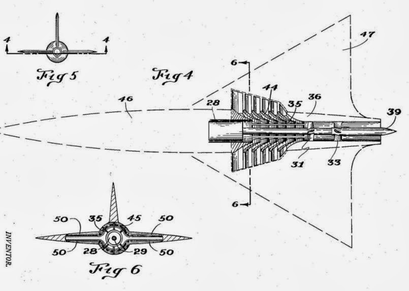
As conventional fuels were in extremely short supply by late 1944, Lippisch proposed that the P.13a be powered by coal. Initially, it was proposed that a wire-mesh basket holding coal be mounted behind a nose air intake, protruding slightly into the airflow and ignited by a gas burner. Following wind-tunnel testing of the ramjet and the coal basket, modifications were incorporated to provide more efficient combustion.The coal was to take the form of small granules instead of irregular lumps, to produce a controlled and even burn, and the basket was altered to a mesh drum revolving on a vertical axis at 60 rpm. A jet of flame from tanks of bottled gas would fire into the basket once the P.13a had reached operating speed (above 320 km/h), whether by using a rocket to assist takeoff or by being towed.
The air passing through the ramjet would take the fumes from the burning coal towards the rear where they would mix under high pressure with clean air taken from a separate intake. The resulting mixture of gas would then be directed out through a rear nozzle to provide thrust. A burner and drum were built and tested successfully in Vienna by the design team before the end of the war.
It is not known what armament would have been carried by the P.13a; the MK 103 cannon would have been too heavy and large for such a small aircraft and it is possible that one or two large-calibre machineguns would have been used.
At the end of the war even the prototype DM-1 test glider had not been finished when it was captured by US forces. It was ordered to be completed by Lippisch's team and was then shipped to the USA where it was test-flown. Reportedly[by whom?] the results were very positive and lessons learned were incorporated into NASA's research aircraft of the 1950s and on.
Film footage exists which shows a gliding test of a scaled-down model of the P.13a. These tests began in May 1944 at Spitzerberg, near Vienna.[2]
Variants
- Akaflieg Darmstadt/Akaflieg München DM.1 - AKA Lippisch DM.1 A scale flying wind tunnel glider version of the proposed Lippisch P.13a
Specifications (P.13a, as designed)
General characteristics- Crew: one
- Length: 6.70 m (22 ft 0 in)
- Wingspan: 6.00 m (19 ft 9 in)
- Height: 3.25 m (10 ft 8 in)
- Wing area: 20.0 m² (215 ft²)
- Loaded weight: 2,295 kg (5,060 lb)
- Powerplant: 1 × Kronach Lorin coal-burning ramjet
- Maximum speed: 1,650 km/h (1,025 mph)
- Range: 1,000 km (621 miles)
- Wing loading: 115 kg/m² (24 lb/ft²)
See also
Akaflieg Darmstadt/Akaflieg München DM1
From Wikipedia, the free encyclopedia
(Redirected from Lippisch DM-1)
| Akaflieg Darmstadt/Akaflieg München DM1 | |
|---|---|
 |
|
| The DM 1 at Munich Prien airport after the war | |
| Role | Full-scale research glider |
| National origin | Germany |
| Manufacturer | Akaflieg Darmstadt & Akaflieg München |
| Designer | Alexander Lippisch |
| Number built | 1 |
| Variants | Lippisch P.13a, Convair XF-92 |
Contents
Development
The DM-series was a joint project of the Darmstadt and Munich Akafliegs. During planning all limits were set aside and, what may seem impossible today was seriously studied, such as the DM4 with a planned wing area of 70m2 (753.5 sq.ft.) expected to reach speeds of 10,000 kilometres per hour (6,200 mph).During World War II Dr. Alexander Lippisch proposed a ramjet propelled point defence fighter Lippisch P.13a. To investigate the low speed handling and aerodynamics of this delta-winged fighter, Lippisch arranged for Akaflieg Darmstadt to build a full-scale flying glider model, which emerged as the Darmstadt D-33. After the Akaflieg Darmstadt workshop was bombed in September 1944, the D-33 project was moved to the Akaflieg München workshops at Prien am Chiemsee. At Prien, Wolfgang Heinemann and Hans Zacher from Darmstadt, with Klaus Metzner and Hermann Nenninger from Munich, completed the D-33 as the Akaflieg Darmstadt/Akaflieg München DM1.
Film footage exists which shows a gliding test of the aircraft. These tests began in May 1944 at Spitzerberg, near Vienna.[2]
The DM1 was built as a single-seat glider from steel-tubing, plywood and bakelite impregnated plywood, with a cockpit in the extreme nose of the junction of the triangular mainplanes and fin. Launching the DM1 was to be by piggy-back or aero-tow.
After liberation by U.S. Troops in May 1945, work continued at the DM1 on behalf of the U.S. military government, with General Patton and Charles Lindbergh visiting Prien to see the project. Completed in early November 1945, the DM1 was shipped in a wooden box to Langley Field in Virginia where the flow behaviour of the DM1 was examined in the NACA (National Advisory Committee for Aeronautics, forerunner of today's NASA) full-size wind tunnel.
While at Langley, the DM1 underwent significant changes. The original design used airfoils of very thick section, especially the vertical stabilizer, which ran all the way to the nose of the aircraft and served double duty as the cockpit. For high speed flight, thicker airfoils are known to have very high drag, which proved to be true on the DM1. The design was progressively modified in an effort to lower drag. One of the first changes was to remove the large vertical stabilizer and replace it with one of much smaller size in a more conventional layout, and adding a normal cockpit canopy taken from a Lockheed P-80 Shooting Star.[3] Further work introduced sharp extensions along the leading edge of the wing, which had the side-effect of showing periodic generation of very large vortexes over the wing.[4] The significance of this effect would not be fully understood until the 1950s.

Specifications (DM1)
Data from DM1 bis DM4[1]
General characteristics- Crew: 1
- Length: 6.32 m (20 ft 8 in)
- Wingspan: 6 m (19 ft 8 in)
- Height: 3.25 m (10 ft 8 in)
- Wing area: ca 19 m2 (204 ft2)
- Empty weight: 375 kg (827 lb)
- Gross weight: 460 kg (1,014 lb)
- Maximum glide ratio: 7
See also
- Related development
- Akaflieg Darmstadt/Akaflieg München DM2
- Akaflieg Darmstadt/Akaflieg München DM3
- Akaflieg Darmstadt/Akaflieg München DM4
- Aircraft of comparable role, configuration and era
Ground effect vehicle
From Wikipedia, the free encyclopedia

Although they might look similar and/or have related technical characteristics, ground effect vehicles are not aircraft, seaplanes, hovercraft, or hydrofoils - ground effect is a separate technology altogether. The International Maritime Organization classifies these vehicles as maritime ships.
Contents
Design
A ground effect vehicle needs some forward velocity to produce lift dynamically and the principal benefit of operating a wing in ground effect is to reduce its lift-dependent drag. The basic design principle is that the closer the wing operates to an external surface such as the ground, said to be in ground effect, the more efficient it becomes.An aerofoil passing through air increases air pressure on the underside, while decreasing pressure across the top. The high and low pressures are maintained until they flow off the ends of the wings, where they form vortices which in turn are the major cause of lift-induced drag – normally a large portion of the drag affecting an aircraft. The higher the aspect ratio of the wing (that is, the longer and skinnier it is), the less induced drag created for each unit of lift and the greater the efficiency of the particular wing. This is the primary reason gliders have long and skinny wings. Placing the same wing near a surface such as the water or the ground has the effect of greatly increasing the aspect ratio, but without having the complications associated with a long and slender wing, so that the short stubs on an Ekranoplan can produce just as much lift as the much larger wing on a transport aircraft, though it can only do this when close to the earth's surface. Once sufficient speed has built up, some GEVs may be capable of leaving ground effect and functioning as a normal aircraft until it approaches its destination. The distinguishing characteristic is that it is unable to land or takeoff without a significant amount of help from the ground effect cushion, and cannot climb until it has reached a much higher speed.
A GEV is sometimes characterized as a transition between a hovercraft and an aircraft, although this is not correct as a hovercraft is statically supported upon a cushion of pressurised air from an onboard downward-directed fan. Some GEV designs, such as the Russian Lun and Dingo, have used forced blowing under the wing by auxiliary engines to increase the high pressure area under the wing to assist the takeoff; however they differ from hovercraft in still requiring forward motion to generate sufficient lift to fly.
Wing configurations
Inverse delta
Developed by Alexander Lippisch, this wing allows stable flight in ground effect through self stabilization. This is the main Class B form of ground effect craft.Ekranoplan wing
This was the profile designed by Rostislav Alexeyev. The wings are significantly shorter than comparable aircraft, and this configuration requires a high aft-placed horizontal tail to maintain stability. The pitch and altitude stability comes from the lift slope[note 1] difference between a front low wing in ground effect (commonly the main wing) and an aft, higher-located second wing nearly out of ground effect (generally named a stabilizer).Tandem wings
Tandem Wing can have two configurations:- a biplane-style Type-1 utilizing a shoulder-mounted main lift wing and belly-mounted sponsons similar to those on combat and transport helicopters
- a canard-style type-2 with a mid-size horizontal wing[note 2] near the nose of the craft directing airflow under the Main Lift Airfoil. This Type-2 tandem design is a major improvement during takeoff as it creates an air cushion to lift the craft above the water at a lower speed, thereby reducing water drag which is the biggest obstacle to successful seaplane launches.
- a Tandem Wing Style with double-wing system as built in Tandem Airfoilboat constructions by Jörg. This system is self-stabilizing and provides secure, comfortable and high-efficiency operation.

Classification
One difficulty which has delayed GEV development is the classification and legislation to be applied. The International Maritime Organization has studied the application of rules based on the International Code of Safety for High-Speed Craft (HSC code) which was developed for fast ships such as hydrofoils, hovercraft, catamarans and the like. The Russian Rules for classification and construction of small type A ekranoplans is a document upon which most GEV design is based. However in 2005, the IMO classified the WISE or GEV crafts under the category of ships.[1]The International Maritime Organization recognizes three classes of ground effect craft:[2]
- Type A: a craft which is certified for operation only in ground effect;
- Type B: a craft which is certified to temporarily increase its altitude to a limited height outside the influence of ground effect but not exceeding 150 m above the surface; and
- Type C: a craft which is certified for operation outside ground effect and exceeding 150 m above the surface.
Advantages and disadvantages

Since most are designed to operate from water, an engine failure may be less hazardous than in a land-based aircraft, but the lack of altitude will leave fewer options to the pilot, negating this benefit. Low altitude brings high speed craft into conflict with ships, buildings and rising land, which may not be sufficiently visible in poor conditions to avoid, and the ground effect vehicle may be unable to climb over or turn sharply enough to avoid them while drastic low level maneuvers risk contacting the earth's surface. The FAA uses the term "controlled flight into terrain" for the primary cause for many aircraft accidents - and they can climb over most obstacles, while ground effect vehicles are more limited.
In high winds, takeoff must be into the wind, which means across successive lines of waves which causes a heavy pounding which both stresses the craft and makes passengers uncomfortable. In light winds, waves may be in any direction, which can make control difficult as each wave causes the vehicle to both pitch and roll. Their light construction limits their ability to operate in higher sea states more than conventional ships, but not so much as with hovercraft or hydrofoils which are closer to the surface of the water. The demise of the seaplane was a result of its inability to take off or land due to sea conditions even while flying conditions were good and its use only lasted until runways were made available. Ground effect vehicles are likewise limited.
Like conventional aircraft, greater power is needed for takeoff, which like a seaplane must first get on the step, before accelerating to flight speed. Careful design and usually multiple redesigns of hullforms is required to get this right increasing engineering costs for ground effect vehicles with short production runs. For the ground effect vehicle to work, its hull needs to be stable enough longitudinally to be controllable, yet not so stable it can't be pulled off the water, while the bottom must be formed to avoid excessive pressures on landing and taking off, without sacrificing lateral stability too badly, and finally it must not create too much spray, which damages the airframe and the engines. The Russian Ekranoplans show evidence of fixes for just these problems in the form of multiple chines on the forward part of the hull undersides, and in the forward location of the jet engines.
Finally, limited utility has kept production levels low where it has been impossible to amortize development costs sufficiently to make them competitive with conventional aircraft.

History
By the 1920s, the "ground effect" phenomenon was well-known, as pilots found that their airplanes appeared to become more efficient as they neared the runway surface during landing. In 1934 the US National Advisory Committee for Aeronautics issued Technical Memorandum 771, Ground Effect on the Takeoff and Landing of Airplanes, which was a translation into English of a summary of research up to that point on the subject. The French author Maurice Le Sueur had added a suggestion based on this phenomenon: "Here the imagination of inventors is offered a vast field. The ground interference reduces the power required for level flight in large proportions, so here is a means of rapid and at the same time economic locomotion: Design an airplane which is always within the ground-interference zone. At first glance this apparatus is dangerous because the ground is uneven and the altitude called skimming permits no freedom of maneuver. But on large-sized aircraft, over water, the question may be attempted ..."[3] By the 1960s, the technology started maturing, in large part due to the independent contributions of Rostislav Alexeyev in the Soviet Union[4] and German Alexander Lippisch, working in the United States. Alexeyev worked from his background as a ship designer whereas Lippisch worked as an aeronautical engineer. The influence of Alexeyev and Lippisch remains noticeable in most GEV vehicles seen today.Soviet Union GEVs
Led by Alexeyev, the Soviet Central Hydrofoil Design Bureau (Russian: ЦКБ СПК) was the center of ground-effect craft development in the USSR; in Russian, the vehicle came to be known as an Ekranoplan (Russian: экранопла́н, экран "screen" + план "plane", from эффект экрана, literally in Russian "screen effect", for "ground effect" in English). The military potential for such a craft was soon recognized and Alexeyev received support and financial resources from Soviet leader Nikita Khrushchev.Some manned and unmanned prototypes were built, ranging up to eight tons in displacement. This led to the development of a 550-ton military ekranoplan of 73 m (240 feet) length. The craft was dubbed the "Caspian Sea Monster" by U.S. intelligence experts, after a huge, unknown craft was spotted on satellite reconnaissance photos of the Caspian Sea area in the 1960s. With its short wings, it looked airplane-like in planform, but would obviously be incapable of flight.[5] Although it was designed to travel a maximum of 3 m (9.8 ft) above the sea, it was found to be most efficient at 20 m (66 ft), reaching a top speed of 300 kn (560 km/h; 350 mph) to 400 kn (740 km/h; 460 mph) in research flights.
The Soviet ekranoplan program continued with the support of Minister of Defence Dmitriy Ustinov. It produced the most successful ekranoplan so far, the 125-ton A-90 Orlyonok. These craft were originally developed as high-speed military transports, and were usually based on the shores of the Caspian Sea and Black Sea. The Soviet Navy ordered 120 Orlyonok-class ekranoplans, but this figure was later reduced to fewer than 30 vessels, with planned deployment mainly in the Black Sea and Baltic Sea fleets.
A few Orlyonoks served with the Soviet Navy from 1979 to 1992. In 1987, the 400-ton Lun-class ekranoplan was built as a missile launcher. A second Lun, renamed Spasatel, was laid down as a rescue vessel, but was never finished. The two major problems that the Soviet ekranoplans faced were poor longitudinal stability and a need for reliable navigation.
Minister Ustinov died in 1985, and the new Minister of Defence, Marshal Sokolov, cancelled funding for the program. Only three operational Orlyonok-class ekranoplans (with revised hull design) and one Lun-class ekranoplan remained at a naval base near Kaspiysk.
Since the dissolution of the Soviet Union, ekranoplans have been produced by the Volga Shipyard[6] in Nizhniy Novgorod. Smaller ekranoplans for non-military use have been under development. The CHDB had already developed the eight-seat Volga-2 in 1985, and Technologies and Transport is developing a smaller version called the Amphistar. Beriev proposed a large craft of the type, the Be-2500, as a "flying ship" cargo carrier,[7] but nothing came of the project.
German GEVs

Hanno Fischer took over the works from RFB and created his own company, Fischer Flugmechanik, which eventually completed two models. The Airfisch 3 carried two persons, and the FS-8 carried six persons. The FS-8 was to be developed by Fischer Flugmechanik for a Singapore-Australian joint venture called Flightship. Powered by a V8 Chevrolet automobile engine rated at 337 kW, the prototype made its first flight in February 2001 in the Netherlands.[9] The company no longer exists but the prototype craft was bought by Wigetworks, a company based in Singapore and renamed as AirFish 8. In 2010, that vehicle was registered as a ship in the Singapore Registry of Ships.[10]
The University of Duisburg-Essen is supporting an ongoing research project to develop the Hoverwing.[11]
German engineer Günther Jörg, who had worked on Alexeyev's first designs and was familiar with the challenges of GEV design, developed a GEV with two wings in a tandem arrangement, the Jörg-II. It was the third, manned, tandem airfoil boat, named "Skimmerfoil", which was developed during his consultancy period in South Africa. It was a simple and low-cost design, but has not been produced beyond a prototype. The prototype has been in the SAAF Port Elizabeth Museum since 4 July 2007 and remains there currently (2013).[12] The consultancy of Dipl. Ing. Günther Jörg was founded with a fundamental knowledge of Wing in Ground Effect physics, as well as results of fundamental tests under different conditions and designs that began in 1960. In 1984, Jörg received the "Philip Morris Award". In 1987, the Botec Company was founded.
GEVs since the 1980s

Besides the development of appropriate design and structural configuration, special automatic control systems and navigation systems are also being developed. These include special altimeters with high accuracy for small altitude measurements and also lesser dependence on weather conditions. After extensive research and experimentation, it has been shown that "phase radio altimeters" are most suitable for such applications as compared to laser altimeter, isotropic or ultrasonic altimeters.[13]
Universal Hovercraft developed a flying hovercraft, a prototype of which first took flight in 1996.[14] Since 1999, the company has offered plans, parts, kits, and manufactured GEV hovercraft called the Hoverwing.[15]
In Singapore, Wigetworks has continued development and obtained certification from Lloyd's Register for entry into class.[16] On 31 March 2011 AirFish 8-001 became one of the first WIG to be flagged with the Singapore Registry of Ships, one of the largest ship registries.[17] Wigetworks has also partnered with National University of Singapore's Engineering Department to develop higher capacity WIG craft.[18]
[19]
Iran deployed three squadrons of Bavar 2 two-seat GEVs in September, 2010. This GEV carries one machine gun and surveillance gear, and incorporates features which reduce its radar signature in a similar manner to stealth.[20]
See also
- Ground effect in aircraft
- Ground effect train
- List of ground effect vehicles
- Hovercraft
- Tupolev N007 ground effect aerosled
- Aerodynamically Alleviated Marine Vehicle
- Seaplane
Dornier Aerodyne
From Wikipedia, the free encyclopedia
| Aerodyne | |
|---|---|
 |
|
| The Aerodyne on display at the Deutsches Museum Flugwerft Schleissheim | |
| Role | Experimental VTOL |
| National origin | West Germany |
| Designer | Alexander Lippisch |
| Built by | Dornier Flugzeugwerke |
| First flight | 18 September 1972 |
| Retired | 30 November 1972 |
| Primary user | BMVg |
| Number built | 1 |
Description
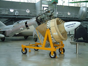
The principle behind the Aerodyne is the combination of lift and thrust production in a single construction unit and flow channel, i.e. a ducted fan. Flaps at the end of the fan divert the outflowing air to produce lift, thrust, or a combination of both. As a result, the Aerodyne could be steered and flown in the entire range between hovering and full-forward flight.For forward flight, the Aerodyne had a conventional tail unit at the rear, which allowed for pitch and yaw control. The equipment was unmanned and operated by remote control.
It was intended to be a land- or ship-supported drone (UAV) for aerial reconnaissance.
Specifications
- Length: 5.5 metres (18 ft)
- Width: 1.9 metres (6 ft 3 in)
- Fan Diameter: 1.1 metres (3 ft 7 in)
- Engine: 1 MTU 6022 A-3, 370 shaft horsepower (280 kW)
- Total Weight: 435 kilograms (959 lb)
Collins X-112
From Wikipedia, the free encyclopedia
| Role | Ground effect vehicle |
|---|---|
| National origin | United States |
| Manufacturer | Collins Radio Company |
| Designer | Alexander Lippisch |
| First flight | 1963 |
| Number built | 1 |
| Developed into | RFB X-113 |
Design and development
Lippisch's development of his Aerofoil Boat, a ground effect vehicle for use over water, began whilst he was working in the aviation division of the Collins Radio Company in Cedar Rapids, Iowa, US. The Collins X-112 was built to test the concept.[1][2]The Airfoil Boat was an inverse delta aircraft, that is it had a wing which was triangular in plan but with a straight, unswept leading edge.[1] Combined with strong anhedral, this layout produces stable flight in ground effect.[3] Specifically, it is claimed that it is stable in pitch and also that it can fly in ground effect at altitudes up to about 50% of its span, allowing it to operate over rough water. This contrasts with the lower aspect ratio square wing of the Ekranoplans which leaves ground effect at only 10% of span, limiting them to the calmer waters of lakes and rivers.[4]
Its fuselage was conventional, with flat sides and rounded decking. The nose-mounted single engine was of very low power, only 25 hp (19 kW). Two open cockpits were arranged in tandem, both over the wing. Aft of the trailing edge root the bottom of the fuselage rose strongly to carry a tall, broad fin and rudder. The X-112 had a T-tail, carrying elevators. Its thick airfoil wings were low mounted, each with a tip float which, in combination with the strong anhedral kept the fuselage well clear of the water surface. Each float carried a steeply sloped short aileron for roll control. A retractable water-rudder, fuselage mounted at the point at which the lower fuselage rose upwards, provided directional control on the water surface.[1]
Tests made during 1963 began with the Airfoil Boat operated like any fast motor boat, planing on the surface. With speeds increased to around 36 mph (58 km/h) the X-112 rose clear of the surface as a ram-air air cushion or ground effect vehicle. Solo free flights at up to 77 mph (124 km/h) were made; tests with two occupants were also conducted. "Entirely satisfactory" stability and control characteristics were reported under all these conditions.[1] With The Airfoil Boat proved, the X-112's mission was completed and Lippisch, suffering from cancer, left Collins Radio. He recovered sufficiently to design and build its successor, the fibreglass, more powerful X-113 with Rhein-Flugzeugbau GmbH in Germany.[2]
Specifications
Data from Jane's All the World's Aircraft[1]
General characteristics- Crew: One or two
- Length: 25 ft 0 in (7.62 m)
- Wingspan: 14 ft 0 in (4.27 m)
- Wing area: 110 sq ft (10 m2)
- Empty weight: 370 lb (168 kg)
- Gross weight: 710 lb (322 kg)
- Powerplant: 1 × unknown, tractor configuration , 25 hp (19 kW)
- Maximum speed: 77 mph (124 km/h; 67 kn) in free flight, flown solo
- Take-off speed: 35-38 mph (55-61 km/h)
By Rob Arndt
Dr. Alexander Lippisch was born in Munich, Germany in 1894.
Known
for his love of delta-winged aircraft he designed a series of
delta-winged gliders in the 1930s that eventually led to the
introduction of the world's first and only rocket-powered interceptor
during WW2 - the Me 163 Komet.


World's greatest test pilot Hanna Reitsch flew both the DFS-194 and Me-163!

Hanna piloting the Reichenberg R-IV
suicide version of the V-1


Lippisch P.13a art

Lippisch P.13a
Art by Daniel Uhr

Hanna Reitsch with Alexander Lippisch, center, and Willy Messerschmitt, right
Lippisch P.13B


Lippisch P.01-111
Art by Tor Pedersen

Messerschmitt-Lippisch P.08 Grosstransporter
DM-1 Mistels

Siebel Si-204D

Siebel Si-204A

Siebel Si-204D

US DC-3 plane

Lippisch Gleit-Bombenflugzeug

Lippisch influence on Ho XIII
During the war Dr.
Lippisch explored a wide range of delta craft and a few circular disc
designs based on the AVA Göttingen K1253 wing profile. His last designs,
however, concerned supersonic deltas and the use of ramjet power.

Lippisch Supersonic Delta
After the war, Dr.
Lippisch's Delta DM-1 glider and delta jet fighter designs led directly
to the Convair XF-92 and subsequently to the highly successful F-102
Delta Dagger and F-106 Delta Dart fighters of the US (which was eager to
apply German delta-wing technology to the emerging jet technology of
the time period). The end product by Convair became the B-58 Hustler.


In Langley Windtunnel in US

Modified version

Convair XP-92 result from wind tunnel testing the DM-1

XP-92 research led directly to the Convair XF-92

Progressive Convair F-102 Delta Dagger

Convair F-106

The ultimate Convair product derived from the DM-1... The B-58 Hustler

Lippisch postwar US Transcontinental Bomber
based on a secret Third Reich bomber concept of 1945
unrelated to the Amerika Bomber program
based on a secret Third Reich bomber concept of 1945
unrelated to the Amerika Bomber program
German work on delta wing planforms, directed by Dr. Alexander Lippisch, led to a US Navy proposal in 1947 for a short-range carrier-based interceptor fighter using a similar layout. Project studies were initiated by the Douglas design team led by Ed Heinemann with the object of producing a fighter optimized for a high rate of climb and capable of intercepting enemy aircraft before they reached their targets. These studies led to a design which, rather than being a pure delta, was a tailless aircraft with a sweptback wing of extremely low aspect ratio, following Dr. Lippisch's own evolution of this layout for the Messerschmitt Me-163 target-defence interceptor.


Douglas F4D Skyray
Meanwhile, Dr. Lippisch
joined American Collins Radio Company in 1950 where he performed
feasibility studies on a wingless VTOL aircraft - his Aerodyne. In
theory, the Aerodyne would outperform conventional aircraft, achieve
supersonic speed, while not suffering the difficulties of "tail-sitter"
configurations like the Convair XFY-1 Pogo, Lockheed XFV-1 Salmon, or
Ryan X-13 Vertijet.

Lippisch designed aerodyne model flight testing at Collins.
World War II but deemed as highly impractica

Another Lippisch aerodyne configuration at Collins
To generate lift and propulsion the Lippisch Aerodyne would utilize two co-axial propellers, the slipstream from each being deflected downwards through flaps for VTOL. Control was to be achieved by deflecting part of the slipstream emerging from the tail boom and by flaps in the propeller flaps. Despite provision for a cockpit, only unmanned craft were built and tested at Collins, operated via electric cables. Collins did manage to construct a full-scale mock up of the Aerodyne and Lippisch patented the idea in 1959.

Lippisch US patent # 2,918,230


Full-scale model of the aerodyne, meant as an unmanned military machine

The massive jet for the aerodyne

Lippisch-Collins Interceptor Drone
In 1967, Dornier picked up the Lippisch Aerodyne concept with the intent on further development. Dr. Lippisch consulted on the craft, now known as the Dornier E-1. The craft was developed from 1968-1971. It was successfully flight tested in 1972 with smooth altitude stabilization and minimal ground effects.


Dornier aerodyne test rig


Lippisch Aerodyne in NASA Ames Wind tunnel
Despite the validation of Dr. Lippisch's Aerodyne design, no operational manned or unmanned craft were built. The Harrier jump-jet, world famous for its VTOL capabilities employs many of Lippisch's VTOL principals.

Lippisch Rescue Aerodyne


What might have been…
Art by I. Shestakov

Ultimate Lippisch Combat Aerodyne

Lippisch vision of the future
After the capitulation of Germany, the well-known German aviation designer Dr. Alexander Lippisch went to the U.S.A. to consult Convair and NACA with their delta-wing fighter development. His work was based on a wartime design for a small ramjet powered delta-wing fighter that was tested as the Lippisch DM-1 glider. The DM-1 was transported to the USA and extensively tested in a wind tunnel. The project for which Lippisch provided his contribution finally resulted in the Convair XF-92. As a next project Lippisch started in the fifties investigations in ground-effect machines. Fitted with a reversed delta wing, it would create an air cushion under the wings that would enable the device to skim just above the water using minimal power output only. This idea became later known as the WIG-concept, where WIG stood for Wing In Ground. This idea was tested in his X-112 design, a small singe-seat craft fitted with a 25 hp engine and built by Collins Radio. Carrying the civil registration N5961V it was successfully 'flown' in 1963.
After these US trials, Lippisch returned to Germany, where another larger proof-of-concept machine was built as the single-seat Lippisch X-113. It was built by Rhein-Flugzeugbau, a subsidiary of Fokker-VFW. Fitted with a 40 hp Nelson H63-CP four-cylinder piston engine, and carrying the civil registration D-9568, it made its first flight in October 1970 from Lake Constance. It was highly successful and the single seat research plane was even capable to fly out of its ground effect up to an altitude of 800 m. However, this needed full power and had excessive fuel consumption as penalty. Based on the X-113, a larger six-seat amphibian version was built as the X-114. It was fitted with a Lycoming piston engine driving a shrouded pusher propeller. It was flown for the first time in April 1977 under a military contract of the German government. It was extensively tested carrying the military markings 98 # 29, but it failed to attract further orders. After the plane crashed due to a pilot error, further work was terminated. Plans for much larger military transport and patrol versions never went beyond the drawing board.

Original Lippisch "Ramwing" TransportConcept

Lippisch X-112


Lippisch X-113

Lippisch X-114
Alexander LIPPISCH
Alexander Martin Lippisch (November 2, 1894 – February 11, 1976) was a German pioneer of aerodynamics. He made important contributions to the understanding of flying wings, delta wings and the ground effect. His most famous design is the Messerschmitt Me 163 rocket-powered interceptor.
Lippisch was born in Munich, Kingdom of Bavaria. He later recalled that his interest in aviation stemmed from a demonstration conducted by Orville Wright, over Tempelhof Field in Berlin, in September 1909.[1] Nonetheless, he planned to follow his father’s footsteps into art school. The outbreak of World War I intervened. During his service with the German Army from 1915–1918, Lippisch had the chance to fly as an aerial photographer and mapper.
Following the war, Lippisch worked with the Zeppelin Company, and it was at this time that he first became interested in tail-less aircraft. In 1921 his first such design would reach production in as the Lippisch-Espenlaub E-2 glider, built by Gottlob Espenlaub. This was the beginning of a research programme that would result in some fifty designs throughout the 1920s and 1930s. Lippisch’s growing reputation saw him appointed the director of the Rhön-Rossitten Gesellschaft (RRG), a glider research group.
Lippisch’s work led to a series of tail-less designs numbered Storch I – Storch IX between 1927 and 1933 (these were not related to the successful Fieseler Fi 156 Storch STOL aircraft of WW2). These designs attracted little interest from the government and private industry. Nonetheless, it was during this time that Lippisch’s Ente (Duck) became the first aircraft to fly under rocket power.
Experience with the Storch series led Lippisch to concentrate increasingly on delta-winged designs. This interest resulted in five aircraft, numbered Delta I – Delta V, which were built between 1931 and 1939. In 1933, RGG had been reorganised into the Deutsche Forschungsanstalt für Segelflug (DFS — "German Institute for Sailplane Flight") and the Delta IV and Delta V were designated as the DFS 39 and DFS 40 respectively.
In early 1939, the Reichsluftfahrtsministerium (RLM — “Reich Aviation Ministry”) transferred Lippisch and his team to work at the Messerschmitt factory, in order to design a high-speed fighter aircraft around the rocket engines then under development by Hellmuth Walter. The team quickly adapted their most recent design, the DFS 194, to rocket power, the first example successfully flying in early 1940. This was the direct ancestor of what would become the Messerschmitt Me 163 "Komet".
Although technically novel, the Komet did not prove to be a successful weapon, and friction between Lippisch and Messerschmitt was frequent. In 1943, Lippisch transferred to Vienna’s Luftfahrtforschungsanstalt Wien (LFW), to concentrate on the problems of high-speed flight. That same year, he was awarded a doctoral degree in engineering by the University of Heidelberg.
Wind tunnel research in 1939 had suggested that the delta wing was a good choice for supersonic flight, and Lippisch set to work designing a supersonic, ramjet-powered fighter, the Lippisch P.13a. wartime test footage By the time the war ended, however, the project had only advanced as far as a development glider, the DM-1.
Like many German scientists, Lippisch was taken to the United States after the war under Operation Paperclip. Advances in jet engine design were making Lippisch's ideas more practical, and Convair became interested in a hybrid jet/rocket design which they proposed as the F-92. [1] In order to gain experience with the delta wing, they first built a jet powered test aircraft, the 7003, which became the first powered delta-wing aircraft to fly. Although the USAF lost interest in the F-92, the 7003 was designated the XF-92A which gave Convair experience with the delta-wing design. This led them to proposing it for most of their projects through the 1950s and into the 1960s, including the F-102 Delta Dagger, F-106 Delta Dart and B-58 Hustler.
From 1950–1964 Lippisch worked for the Collins Radio Company in Cedar Rapids, Iowa, which had an aeronautical division. It was during this time that his interest shifted toward ground effect craft. The results were an unconventional VTOL aircraft (an aerodyne) and an aerofoil boat. However, Lippisch contracted cancer, and resigned from Collins.
When he recovered in 1966, he formed his own research company, Lippisch Research Corporation, and attracted the interest of the West German government. Prototypes for both the aerodyne and the ground-effect craft were built, but no further development was undertaken. The Kiekhaefer Mercury company was also interested in his ground-effect craft and successfully tested one of his designs as the Aeroskimmer, but also eventually lost interest.
Lippisch died in Cedar Rapids early in 1976.
Other Aircraft Designed by Lippisch
Lippisch P.01-111, designed as a competitor to the Messerschmitt Me-163 Komet.
Lippisch Li P.04-106, a tailless airplane designed as a competitor to the Messerschmitt Me 329
Lippisch P.11, designed to compete with the Horten Ho-IX; the latter went on to become the Horten (Gotha) Ho-(Go-)229.
Lippisch P.13a, a unique delta-winged, ramjet-powered interceptor.
Lippisch P.13b, a unique airplane powered by a rotating fuel-table of lignite, owing to the fuel shortages late in World War 2 in Germany.
Lippisch P.15, a development of the Messerschmitt Me-163 Komet.
Alexander Lippisch Photograph Collection, [ca. 1920s-1950s]
Creator: Lippisch, Alexander, 1894-1976
Title: Alexander Lippisch Photograph Collection, [ca. 1920s-1950s]
Phy. Description: 0.90 cubic feet (2 legal document boxes)
Bio / His Notes:
Alexander Lippisch (1894-1976) began his career in Aeronautics in February, 1918 when he joined the aircraft manufacturing plant of Zeppelin-Dornier in Lindau, Germany as an aerodynamicist. In 1921 Lippisch began his work on the development of sailplanes and gliders. At the same time he worked on the development of the tailless and the Delta-wing aircraft. In 1939 Lippisch joined the Messerschmitt A.G. Augsburg for the development of the ME 163 A and B. In 1943, Lippisch took over the Aeronautical Research Institute (LFW) were he developed the shape of the supersonic Delta wing. After the war, he was in custody of the Air Technical Intelligence of the U.S. Army. Lippisch was transferred to the United States where he worked at Wright Field, for the Navy, and later with Collins Radio Company. At Collins he developed a wing-less aircraft, the Aerodyne. He also started the development of another type of aircraft - the ram-wing or Aerofoil Boat.
Summary:
This collection contains photographs and drawings of the tailless and all-wing aircraft with which Lippisch was involved. Many of the photographs appear in Lippisch's book 'The Delta Wing: A History and Development.'
Alexander Lippisch was born in Munich, Germany in 1894. Developing an affinity for delta-winged aircraft, he designed a series of innoative gliders during the 1930s, his concepts ultimately resulting in World War II's rocket-powered ME163 "Komet" interceptor. In 1950, Lippisch joined the American Collins Radio Co. where he investigated the feasibility of building a high-performance Vertical Take-Off and Landing (VTOL) aircraft. The "Aerodyne" was the most interesting of his concepts: Theoretically, it would be able to outpace most conventional aircraft with the same weight/power ratio, it would be able to achieve super-sonic speed, and it didn't have the operational disadvantages of such "tail-sitters" as the Convair XFY-1 "Pogo," Lockheed's XFV-1 "Salmon," or the Ryan X-13 "Vertijet."
The Aerodyne's lift and propulsion were to be generated by two co-axial shrouded propellers, the slipstream from which would be deflected downward by "flaps" for vertical take-off and landing. Control was to be achieved by deflecting part of the slipstream emerging from the end of the tail boom, and by flaps in the propeller slipstream.
Lippisch's fundamental equations survive on paper, and this Sharkit represents one of the many models built for research purposes. Despite the drawn cokpit, only unmanned craft were built and tested.
The Aerodyne configuration was ultimately validated by the Dornier aerodyne "E1," a high-speed VTOL drone developed between 1968 and 1971, and succesfully fight-tested in 1972. Hovering flight tests showed extremely smoth attitude stabilization and minimal ground-effects.
And, of course, the McDonnell-Douglas Harrier Jump Jet, developed in the 1970s and still in operation today, employs many of Lippisch's VTOL principles.
Alexander Lippisch Digital Collection
Alexander Lippisch Papers (1897-1993, n.d.) located in Special Collections, contains biographical material, correspondence, scientific research, materials relating to patents, publications, photographs, and films. In addition to a rich array of material relating to Lippisch's work in aeronautical engineering, the collection also includes biographical material about Lippisch and publications and photographs related to general aviation history.
Scientific files document Lippisch's work designing sailplanes and gliders, delta winged aircraft, and aerodynes, as well as research involving aerodynamics, smoke tunnels, and ground effect. These files include materials such as calculations, data, statistics and experimental test results, and technical designs and conceptual drawings of aircraft designs. The collection also includes copies of patent applications for Lippisch's work as well as the work of other aeronautical engineers.
Alexander Lippisch Digital Collection contains the technical designs and conceptual drawings for Lippisch's aeronautical designs including wingless aircraft, delta-wings, and aerodynes, as well as numerous photographic images of delta wings.
No comments:
Post a Comment