

.jpg)


Avro Canada VZ-9 Avrocar
From Wikipedia, the free encyclopedia
| VZ-9 Avrocar |
 |
| The Avrocar S/N 58-7055 (marked AV-7055) on its rollout. |
| Role |
experimental "proof-of-concept" VTOL vehicle |
| National origin |
Canada |
| Manufacturer |
Avro Aircraft Ltd. (Canada) |
| Designer |
John Frost |
| First flight |
12 November 1959 |
| Introduction |
1958 |
| Retired |
1961 |
| Status |
experimental |
| Primary users |
United States Air Force (intended)
United States Army (intended) |
| Produced |
1958–1959 |
| Number built |
2 |
| Unit cost |
Project cost: $10 million (USD) [1] |
The
Avro Canada VZ-9 Avrocar was a
VTOL aircraft developed by
Avro Aircraft Ltd. (Canada) as part of a secret U.S. military project carried out in the early years of the
Cold War.
[2] The Avrocar intended to exploit the
Coandă effect
to provide lift and thrust from a single "turborotor" blowing exhaust
out the rim of the disk-shaped aircraft to provide anticipated
VTOL-like performance. In the air, it would have resembled a
flying saucer.
Originally designed as a
fighter-like aircraft capable of very high speeds and altitudes, the project was repeatedly scaled back over time and the
U.S. Air Force eventually abandoned it. Development was then taken up by the
U.S. Army for a tactical combat aircraft requirement, a sort of high-performance
helicopter.
[3]
In flight testing, the Avrocar proved to have unresolved thrust and
stability problems that limited it to a degraded, low-performance
flight envelope; subsequently, the project was cancelled in September 1961.
Through the history of the program, the project was referred to by a
number of different names. Avro referred to the efforts as Project Y,
with individual vehicles known as Spade and Omega. Project Y-2 was later
funded by the U.S. Air Force, who referred to it as WS-606A, Project
1794 and Project Silver Bug. When the U.S. Army joined the efforts it
took on its final name "Avrocar", and the designation "VZ-9", part of
the U.S. Army's VTOL projects in the VZ series.
Design and development
Origins
The Avrocar was the ultimate result of a series of
blue skies research projects by designer
"Jack" Frost, who had joined Avro Canada in June 1947 after working for several British firms.
[4] He had been with
de Havilland from 1942 and had worked on the
de Havilland Hornet,
de Havilland Vampire jet fighter and the
de Havilland Swallow aircraft, where he had been the chief designer on the supersonic research project.
[5]
At Avro Canada, he had worked on the
Avro CF-100
before creating a research team known as the "Special Projects Group"
(more commonly known as SPG). Frost first surrounded himself with a
collection of like-minded "maverick" engineers, then arranged for a work
site. Initially ensconced in the "Penthouse" (the derisive company
nickname for the executive wing) of the Administration Building, the SPG
was subsequently relocated to a
Second World War-era
structure across from the company headquarters, the Schaeffer Building,
that was secured with security guards, locked doors and special pass
cards. At times, the SPG also operated out of the Experimental Hangar
where it shared space with other esoteric Avro project teams.
At the time, Frost was particularly interested in jet engine design
and ways to improve the efficiency of the compressor without sacrificing
the simplicity of the turbine engine. He found
Frank Whittle's
"reverse flow" design too complex and was interested in ways to "clean
up" the layout. This led him to design a new type of engine layout with
the
flame cans lying directly outside the outer rim of the
centrifugal compressor, pointed outwards like the spokes on a wheel. Power for the compressor was drawn from a new type of turbine similar to a
centrifugal fan,
as opposed to the more typical pinwheel-like design of conventional
engines. The turbine drove the compressor using gearing, rather than a
shaft. The resulting engine was arranged in the form of a large disk,
which he referred to as a "pancake engine."
[6]
The jet thrust exited from around the entire rim of the engine, and
this presented problems trying to adapt the design to a typical
aircraft.
Project Y

Rare colour image from an Avro Aircraft company film showing the Project
Y mock-up in the Experimental Flight Hangar c. 1954. The edge of the
wing closest to the camera shows the scalloped nozzles used to redirect
the jet thrust rearward. The cockpit is just visible at the front of the
"spine" running along the top of the aircraft. Note the spade-like
shape of the planform.
At the same time, the aircraft industry as a whole was becoming increasingly interested in
VTOL
aircraft. It was expected that any future European war would start with
a nuclear exchange that would destroy most airbases, so aircraft would
need to operate from limited airbases, roads or even unprepared fields.
Considerable research effort was put into various solutions to securing a
second-strike capability. Some of these solutions included
rocket-launched aircraft like the
zero-length launch concept, while many companies started work on VTOL aircraft as a more appropriate long-term solution.
[7]
Frost felt the excellent performance of his new engine would be a natural fit for a VTOL aircraft due to its high expected
power-to-weight ratio.
The problem was how to use the annular thrust to drive the aircraft
forward, as well as the problem of fitting the very large engine into a
suitable airframe. Frost suggested using a series of vents to redirect
the thrust flowing out of the "front" of the engine towards the rear,
although it was well known that long channeling leads to a loss of
thrust. In order to keep the "piping" as short as possible, the design
ported the thrust out along the leading edge of what was essentially a
very large
delta wing. As the engine was disk-shaped, the triangular shape was "pushed out" near the front, producing a
planform shaped roughly like a
spade.
[6]
For this reason the design was also referred to as the "Avro Ace," a
likely reference to the Ace of Spades. The compressor inlet was located
at the middle of the engine, so the engine air intakes were located just
to the front of the centre on the top and bottom of the aircraft. The
cockpit was positioned over the main bearing, behind the intakes. A
"spine" on the top and bottom ran from the cockpit area to the rear edge
of the aircraft. Several other versions of the basic layout were also
studied, including the "Omega" which was more disk-like as it cut away
the rear portions of the delta wing as well.
For VTOL operations the aircraft was expected to sit pointed up,
supported by long landing legs that extended out of the spine. Landing
would be accomplished at a very high angle, making visibility during the
approach very difficult. A number of other VTOL experiments of the era
attempted various solutions to this problem, including rotating pilots
seats and cockpits, but none proved very effective. Another problem with
various VTOL experiments was that stability in a hover was difficult to
arrange, although not entirely unexpected. A solution to this problem
would require the thrust to be directed downward from a larger area, as
it is in a helicopter, where the lift is supplied over the entire area
of the rotor disk.
[3]
Most designers turned to bleeding off air from the engine's compressor,
and directing that through pipes arranged around the aircraft. Frost's
engine design used such a large number of nozzles that such an
arrangement would not be to easy to build.
In 1952, the design was advanced enough that the Canadian
Defense Research Board
funded the effort with a $400,000 contract. By 1953, a wooden mock-up
of Project Y was completed, of which only images remain. It appears the
project was considered too costly within the military establishment,
which was at the time involved in several extremely expensive air
defense projects. On 11 February 1953, a story on the project was leaked
to the
Toronto Star
along with images of the Omega design, apparently in order to gain
further funding (a strategy widely employed in the U.S. at the time,
known as
policy by press release).
Five days later, the Minister for Defense Production informed the House
of Commons that Avro was indeed working on a "mock-up model" of a
flying saucer, capable of flying at 1,500 miles per hour (2,400 km/h)
and climbing vertically. Nevertheless, further funding was not
forthcoming.
Project Y-2: the "flat-riser"

"Jack" Frost demonstrates the Coandă effect. Pressurized air flows out
of the end of the red tube, and then over the top of the metal disk. The
Coandă effect makes the air "stick" to the disk, bending down at the
edges to flow vertically. This airflow supports the disk in the air.
While Project Y continued, Frost had meanwhile become interested in the
Coandă effect,
where fluid flows will follow strongly convex shapes, something that
might be unexpected at first glance. Frost felt the effect could be used
with his engine design to produce a more practical VTOL aircraft, the
exhaust flowing outward over the upper surface of the aircraft and then
being directed downward over a flap-like arrangement. This would produce
a lift force around the entire edge of the aircraft, allowing it to
land "flat". He produced a number of small experimental designs using
compressed air in place of an engine in order to select a suitable
planform shape, and eventually decided that a disk was the best solution.
[8]
As he continued these experiments, he found that the same
thrust-direction system he intended for VTOL operations worked just as
well for forward flight. In this case the disk shape was not of itself a
good lifting surface, as it was neutral in terms of lift direction –
that is, it would fly sideways as readily as it would fly forward.
However, by modifying the airflow with the application of a small amount
of jet thrust, the overall airflow over the craft could be dramatically
altered, creating a sort of "virtual airfoil" of any needed
configuration. For instance, by directing even a small amount of jet
thrust down, a large mass of air would be pulled over the upper surface
of the wing and dramatically augment the flow over the wing, creating
lift.
[9]
This appeared to offer a solution to one of the most vexing problems
of the era, designing an aircraft that was effective at subsonic and
supersonic speeds. Subsonic lift is created by the airflow around the wing following
streamlines, but supersonic lift is generated by
shock waves
at points of critical curvature. No single design could offer high
performance for both regimes. The blown disk could attack this problem
by being laid out for supersonic performance only, and then using jet
thrust to modify subsonic airflow into a semblance of a normal wing. The
resulting design would be tuned for high supersonic performance, have
reasonable subsonic performance, and would also offer VTOL, all in a
single design.
U.S. Involvement: Project 1794/WS 606A

Avro company models of the Y-2 (right) and the Avrocar (left)
In late 1953, a group of U.S. defence experts visited Avro Canada to view the new CF-100 fighter jet.
[10]
Somewhere along the way, Frost co-opted the tour and rerouted it to the
Special Projects area where he proceeded to show off the Project Y
mock-up and models and drawings (some never before seen by senior
company officials) for a completely circular disk-shaped aircraft known
as "Project Y-2." The USAF agreed to take over funding for Frost's
Special Projects Group, and a contract for US$750,000 followed in 1955.
By 1956, Avro management was interested enough to commit $2.5 million to
build a "private venture" prototype. In March 1957, the Air Force added
additional funding, and the aircraft became
Weapons System 606A.
A wide variety of designs were studied for a VTOL fighter aircraft,
[3]
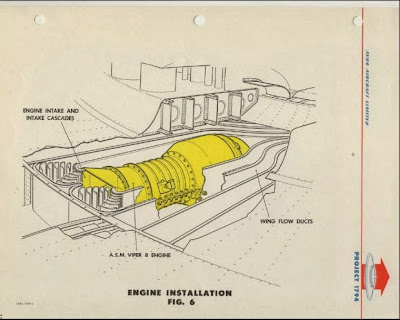
all revolved around the disk shape, leading to the Project 1794
involving a supersonic large disk fighter aircraft. The concept
proceeded to wind tunnel testing with a variety of scale models. It
featured a raised section in the middle over the engine, the intake
covered with a series of louvers that would be closed in forward flight.
Frost's performance estimates for the concept were for a potential of
Mach 3.5 at 100,000 ft (30,000 m) altitudes.
There was some debate about the concept within the USAF, as many
groups were attempting to gain funding for their own pet projects, like
nuclear powered bombers.
[11] In a repeat of the earlier Toronto Star release, in 1955 an extensive article appeared in
Look magazine that, among other claims, speculated that current
UFO
sightings were Soviet-built saucers. The article went on to describe
such an aircraft with diagrams that were clearly influenced by the Avro
design.
[12]
A new impeller-driven engine design was proposed as Avro PV-704 (PV stood for Private Venture), powered by six
Armstrong Siddeley Viper
jet engines blowing across the outer rim of a central rotor. The PV-704
was a "stop-gap" design built into a bunker-like building behind the
Avro Experimental Test facility. It was intended to test various Project
1794 concepts and provide the USAF with test data to show the viability
of the concept. The original plan to initially test the "Viper Engine
Rig" was to have continued into "free flight" testing. Unfortunately,
testing was anything but smooth; the test model suffered from hazardous
oil leaks, resulting in three fires.
[13]
It eventually got to the point that staff were afraid of the machine,
even when safely ensconced in a booth constructed of bullet-proof glass
and quarter-inch-thick steel. A final, disastrous and nearly lethal
engine test in 1956 which involved a Viper jet engine "running wild"
convinced Frost that a less dangerous test vehicle was necessary.
Genesis of the Avrocar
To gather flight data on the basic concept while the engine
development continued, in 1958 Frost proposed building a smaller
"proof-of-concept" test vehicle he called the
Avrocar. By this
point, the U.S. Army was involved in a wide variety of experiments on
smaller VTOL aircraft that would act as a "flying Jeep,"
[14] and they became interested in Avro's concept as well.
[15]
Frost pitched his smaller design both as a prototype of a vehicle
suitable for the Army's needs, as well as an aerodynamic testbed for the
WS-606. Initial performance requirements for the Avrocar were a
ten-minute hover capability in ground effect and 25-mile (40 km) range
with a 1,000 lb (450 kg) payload.
[15]

U.S. Army Avrocars depicted as "flying jeeps" in company literature
The new plan appeared to make everybody happy, and a $2 million joint-services contract
[16] managed by the Air Force was awarded to Avro to build and test two Avrocars, which the Army referred to as the
VZ-9-AV (with AV standing for "Avro," an unusual departure from normal U.S. Army nomenclature
[17]),
the latest in a series of "VZ" aircraft. Army interest in the Avrocar
program was apparently very high. Bernard Lindenbaum of the Air Force
Flight Dynamics Laboratory recalls a trip to Washington in the late
1950s to request additional funding for a study on helicopter drag
reduction. Although the funding was approved, he overheard an Army
General remark that the
Huey would be the last helicopter the Army would buy since the helicopter would be replaced by the Avrocar.
[15]
Additional Air Force funding of approximately $700,000 (unexpended
from the 606A program) was also moved to the Avrocar project. In March
1959, an additional $1.77 million contract was received for a second
prototype. At rollout, projected performance was far in excess of the
requirement, with a 225 knots (417 km/h) maximum speed, 10,000 feet
(3,000 m) ceiling, 130-mile (209 km) range with 1,000 lb (450 kg)
payload, and hover out of ground effect with 2,428 lb (1,101 kg)
payload. Maximum takeoff weight with transition to forward flight out of
ground effect was calculated to be 5,650 lb (2,560 kg), maximum weight
with a transition in ground effect (GETOL) was 6,970 lb (3,160 kg).
[15]
Just as the first working test models were being manufactured, disaster struck. The Canadian government cancelled the Avro
CF-105 Arrow
program on "Black Friday," 20 February 1959. The ensuing result was the
lay-off of almost all Avro Canada employees, including those with the
Special Projects Group. However, three days following the announcement
of the Arrow cancellation, many of the Special Projects employees were
rehired. But it wasn't quite business as usual. The team now included
people from the CF-100 and CF-105 teams and the Special Projects Group
was moved into the main building, which was nearly empty. As well,
company "brass" became more involved in the group’s operations.
[18]
The USAF Project Office devoted to the Avro projects, recommended
that the WS-606A and all related work (including the Avrocar) be
cancelled. A "stop/go"
[19]
work order came down and Frost was forced once more to try to rescue
the project. In an elaborate effort, Frost made a resounding case for
continuation of U.S. military funding. Late in May 1959, the USAF
authorized Avro to continue the "flying saucer" programs.
[20]
Design

Avrocar schematic from the VZ-9 manual
The Avrocar was a disk-shaped aircraft with the same basic shape as a
frisbee,
the upper surface of the disk being fairly curved, and the bottom much
less so. The disk was 18 feet (5.5 m) in diameter and 3.5 feet (1.1 m)
thick. The main structural truss was a large equilateral triangle, to
which the various components were attached. The 124-blade "turborotor"
sat in the center of the triangle, with most of the rotor's thrust
directed straight down through an opening in the lower surface, but some
was bled off to power the control system running along the outer rim of
the disk.
[21] Power for the rotor was provided by three
Continental J69-T-9
jet engines attached to the truss. Each engine had its own fuel and oil
tanks and other support systems, although it was expected these would
be interconnected in future models. The majority of the airframe was
made of aluminum with an empty weight of 3,000 pounds (1,400 kg).
[22]
Pilot control was entirely through a single side-mounted control
stick. Pitch and roll were controlled through conventional fore-aft and
side-to-side motions, while yaw could be controlled by twisting the
stick. No mechanical linkages were used, the stick instead controlled
the flow of high pressure air around the craft, which either directly
attached to various control surfaces, or indirectly through local cable
linkages to replace controls that were intended to be cable-actuated
(like throttle controls on the engines).
[21]
The attitude/thrust control system consisted of a large ring situated
outside of the main disk, shaped roughly like a rounded triangle with
the flat surface on the "inside." Viewing the craft from the side, the
control flap is almost invisible, appearing in its neutral position to
blend into the profile. The pilot's controls moved the ring in relation
to the rest of the craft, affecting the airflow moving outward from the
center of the craft. Vertical lift could be increased by moving the
entire ring down, which would produce more airflow over its upper
surface, which would then bend down over this surface toward the ground.
Tilting the ring resulted in asymmetric thrust for directional control.
[23]
It was discovered that the craft was inherently unstable in forward flight, as the aerodynamic
center of pressure was well forward of the
center of gravity.
[24] The Avrocar thus included a mechanical
stability control system that was independent of the pilot's controls. The turborotor had a fairly large
angular momentum and was intended to act as a powerful
gyroscope,
providing a "normal" direction of flight. Control cables attached to
the base of the rotor would be pulled when the craft moved in relation
to the rotor, actuating the control surfaces to counteract the motion.
The vehicle was manned by a crew of two, positioned in separate
cockpits squeezed into empty areas in the airframe. In practice, only
one pilot was usually on board during testing; a number of flights were
made with an observer in the second cockpit. Until control problems were
completely solved, the Avro test pilots acquired a "touch" for the
extremely sensitive control inputs and Avro Aircraft Chief Development
Test Pilot Potocki was eventually able to demonstrate a "hands-off"
flight. Nonetheless, Avro test pilot Peter Cope, USAF project pilot
Walter J. Hodgson and NASA Ames Chief Test Pilot Fred J. Drinkwater III,
who all flew the Avrocar, considered it still a tricky vehicle to fly.
Drinkwater likened a flight in it to "balancing on a beach ball."
[25]
The undercarriage of the Avrocar was rudimentary with three small
castoring wheels mounted on "stub" shafts; a set of skids was
substituted later in testing although they were not normally fitted.
[26]
Operational history
Testing

The first Avrocar being readied at the Avro factory c.1958
The first Avrocar, #
58-7055, rolled out of the Avro Malton factory in May 1959. From 9 June to 7 October 1959, it was tested in a static hover rig.
[27]
Unfortunately, hot gas from the exhaust was found to mix back into the
intakes in hover, reducing engine thrust. In addition, the fan generated
lift only from a small area of its surface, lowering overall thrust
available. The ducts also proved to have higher losses than expected,
and a series of modifications were not able to solve this problem to any
large degree. These problems reduced maximum lift at higher altitudes
out of the ground effect to 3,150 lb (1,430 kg), less than the empty
weight of the aircraft at 4,285 lb (1,944 kg). This meant the aircraft
would be incapable of hovering out of the ground effect. Following these
tests, the vehicle was sent to
NASA Ames for a wind tunnel testing.
The second, #
59-4975, was completed August 1959. On 29 September, the first attempt to hover was made with the Avrocar tethered to the ground.
[28]
After the vehicle became airborne, an uncontrollable roll and
pitch-coupled oscillation started that forced each of the three wheels
into the ground in turn. The pilot, W.D. "Spud" Potocki, immediately
shut down all engines. Changes were made to the stability system to
provide more control authority, while new tethers were investigated to
improve the ability to control these sorts of problems.
[3]
As testing continued it became clear that the problem was inherent to
the design, and the engineers started referring to the effect as
"hubcapping," so-named as it appeared similar to a hubcap spun on the
ground.
[29]
Investigations into the effect revealed what was causing the problem.
While in the ground effect, the high-pressure air under the craft was
trapped, filling the entire area and thus providing a stable base. When
the craft rose out of the ground effect, the air formed itself into a
single narrow column, described by Frost as "tree trunking". At
intermediate altitudes the craft would momentarily transition from one
regime to the other, during which time one side of the vehicle would be
entirely supported while the support was disappearing under the other.
This led to a strong pitching motion towards the unsupported side. As
soon as this occurred that side would approach the ground and
re-establish the supporting air, while the other side would then be
raised above this limit. This process would repeat itself, with the
craft rolling from side to side. Modifications were carried out in order
to try to solve the problem. Eventually a series of 52 holes were
drilled in the bottom of the vehicle, located radially three feet from
the center. These were to provide a central jet to stabilize the ground
cushion.
[30]
With these modifications complete and apparently working, the first
completely free flight occurred on 12 November 1959. This test proved
the nozzle control system unacceptable. The spoilers were intended to
direct the air out over the top or bottom of the annular flap, out the
bottom only during hover, but over the top and bottom during forward
flight. The idea was that when the flap was positioned in order to
provide control, the lift would be lowered on one side and raised on the
other. Lift was indeed lowered on one side, but sadly the lift did not
improve on the other, so every control input resulted in a loss of
altitude. After five flights, testing was temporarily halted on 5
December 1959, by which time the Avrocar had logged 18.5 hours of test
time in total.

Avrocar
59-4975 after modifications, was tested without the
canopies and incorporating the perimeter "focusing" ring c. 1961. Tests
showed that the heat was so oppressive that all instruments were baked
brown after only a few flights.
A completely new design was installed over the winter. The original
spoilers were removed and replaced by a single ring below the annular
flap. The ring shifted in relation to the craft under control input,
"sealing off" the gap on one side while opening it on the other. Tests
continued in January 1960, and appeared to work much better. However,
while the new control system improved the hovering qualities, the craft
now became unstable at higher speeds above 30 knots (56 km/h). The first
Avrocar at Ames was similarly modified, and, in April 1960, it was
tested in their 40 x 80 ft (24 m) wind tunnel.
[31]
The problem became clear; the ring blocked so much of the overall
engine thrust that the overall power was greatly reduced. As the craft
sped up, the airflow on the underside reduced the recirculation,
reducing the lift due to airflow over the upper surface. This was
somewhat unexpected; recirculation had been considered a "bad thing" due
to the loss of engine thrust, and its positive effects on lift do not
appear to have been appreciated. In the end, in order to maintain lift
at higher forward speeds the craft had to be pitched to the end of its
control capability.
Avro was convinced that the concept was still workable, and proposed a
new program for major rework of the propulsion and control system.
Instead of the single annular triangular flap and spoilers, or the later
ring control, the new system included two separate control systems for
hover and forward flight, combined into a single nozzle. For hover, a
series of "transition doors" were opened into the nozzles, blocking them
off and re-directing the flow downward under the aircraft. Control
during this regime was provided by moving the outer portion of the flap
to "focus" the flow. At higher speeds, the doors were closed, allowing
the air to flow out from the edge of the aircraft, where a series of
simple flap-like controls were located. The new control system covered
the rear 3/4's of the aircraft's outer circumference; the front section
featured the hovering controls only.
[26]
Modifications were completed on the Ames model and testing resumed in
April 1961. The new design demonstrated much better control in hover
and considerably improved lift. The vehicle was now able to travel at up
to 100 knots (190 km/h), a great improvement over the 30 knots
(56 km/h) previously reached. However, it remained unstable in pitch,
and exhibited a strong nose-up trim. NASA engineers attempted to modify
this with a
T-tail,
but this proved to sit within the airflow of the turborotor and did not
help. Frost's team considered two new designs, one with a large
vertical tail and one with a wing with tip mounted verticals
—"winglets." Both designs used two 2,700 lbf (12 kN) thrust
General Electric J85 turbojets and increased the turborotor diameter from five to six ft.
[32]
On 9 June 1961, a second USAF/NASA flight evaluation of the Avrocar
was conducted on the similarly modified second prototype at the Avro
facility. During these tests, the vehicle reached a maximum speed of 20
knots (37 km/h) and showed the ability to traverse a ditch six feet
across and 18 inches (460 mm) deep. Flight above the critical altitude
proved dangerous if not nearly impossible due to inherent instability.
[1] The flight test report further identified a range of control problems.
[33]
Cancellation
Before modifications could be achieved, funding ran out in March
1961. Frost's proposals for a modified design were not accepted, and the
Avrocar and related WS-606A supersonic VTOL programs were officially
cancelled in December 1961 by the U.S. military. Avro company executives
encouraged additional VTOL research projects, exploring new
configurations married to a disk platform
[1]
and even a "lift jet" version, but no further interest resulted from
Canadian or other sources, to cap the end of this Special Projects Group
program. In 1961, a number of later proposals, including the Avro P470
VTOL fighter concept derived from the Special Projects Group, were
submitted to fulfill a NATO competition for a tactical strike fighter.
[34] These needs were filled by the
Hawker Siddeley Harrier,
but in more general terms, interest in VTOL faded as it became widely
believed a nuclear first strike would not be used at the start of a
European war.
The second Avrocar had logged about 75 flight hours at the end of the
flight testing. Judged by its performance, the Avrocar was an abject
failure: it couldn't lift itself safely more than a few feet off the
ground, and its bulbous design limiting high-speed performance
accompanied by unbearable heat and screaming exhaust noise, made it
impractical for the military. Although considered a technical failure,
its design would be prophetic: it was a rubber skirt shy of being one of
the world's first
hovercraft, the
Saunders Roe SR.N1
also taking off in 1959. Nevertheless, company designer, John Frost
applied for a number of patents in Canada, the UK and the U.S. that
established the pivotal role that the Avrocar and related Avro
experimental vehicles, made in the VTOL world.
[5][35]
Latest developments
The Avro VZ-9 Avrocar was a "dead end" in VTOL design, according to Russell Lee, curator at the
National Air and Space Museum,
yet its technological innovations have intrigued other designers. One
of the design elements it embodied, the use of ducted fans led to other
experimental programs. Dr. Paul Moller, a Canadian expatriate who had
worked at Avro Canada as a young engineer, based an initial series of
experimental VTOL vehicles on "saucer" technology utilizing the buried
ducted fan à la-Avrocar. The XM-2, the first of the series looked
remarkably like a miniature flying saucer. After successful tether tests
[citation needed], the saucer designs also at one time publicized as "discojet" were abandoned and their latest project, the
Moller Skycar, has a flying-car appearance.
[36]
The Avrocar story did not end with the termination of the program.
Only two Avrocars were ever produced and because the U.S. military had
paid for the work, they reverted to U.S. ownership at the end of the
program. The second example, S/N
59-4975, utilized for "flight" testing, returned to Canada briefly for display in Montreal at the
Man and His World Exhibition (1968); after a lengthy period of outdoor display, it is now under restoration at the
U.S. Army Transportation Museum in Fort Eustis, Virginia.
[16]

Avrocar at the National Museum of the United States Air Force in Dayton, Ohio
The first Avrocar, S/N
58-7055 (marked
AV-7055), after
tethered testing, became the "wind tunnel" test model at NASA Ames,
where it remained in storage from 1961 until 1966, when it was donated
to the
National Air and Space Museum, in
Suitland, Maryland.
There it continued gathering dust for the next forty years. The Museum
finally scheduled it for restoration and display at their newly
constructed
Steven F. Udvar-Hazy Center. Instead the Avrocar has been loaned to the
National Museum of the United States Air Force in
Dayton, Ohio,
arriving in November, 2007. After a full restoration, which included
fabrication of both missing plexiglass bubbles, it was put on display in
June 2008 in the Museum's Cold War Gallery. It has since been moved to
the Presidential Aircraft Gallery.
A full-scale replica of the Avrocar was prepared for the 2002 production,
Avrocar: Saucer Secrets from the Past. It now resides as an exhibit at the
Western Canada Aviation Museum,
Winnipeg,
Manitoba, Canada.
Specifications (VZ-9-AV)
Data from Avrocar: Canada's Flying Saucer...[37] and
The World's Worst Aircraft: From Pioneering Failures to Multimillion Dollar Disasters[38]
General characteristics
- Crew: 2
- Capacity: 1 observer/engineer
- Diameter: 18 ft (5.5 m)
- Height: 3 ft 6 in (1.07 m)
- Wing area: 254 sq ft (23.6 m2)
- Empty weight: 3,000 lb (1,361 kg)
- Max takeoff weight: 5,560 lb (2,522 kg)
- Powerplant: 3 × Continental J69-T-9 turbojet engines, 660 lbf (2.9 kN) thrust each
Performance
- Maximum speed: 300 mph (483 km/h; 261 kn) (estimated), 35 mph (56 km/h) (actual)
- Range: 995 mi (865 nmi; 1,601 km) (estimated), 79 mi (127 km) (actual)
- Service ceiling: 10,000 ft (3,048 m) (estimated), 3 ft (0.91 m) (actual)
Coandă effect
From Wikipedia, the free encyclopedia

A spinning ping pong ball is held in a diagonal stream of air by the
Coandă Effect. The ball "sticks" to the lower side of the air stream,
which (in combination with the
Magnus effect)
stops the ball from falling down. The jet as a whole keeps the ball
some distance from the jet exhaust, and gravity prevents it from being
blown away.
The
Coandă effect // is the tendency of a
fluid jet to be attracted to a nearby surface.
[1] The principle was named after
Romanian aerodynamics pioneer
Henri Coandă, who was the first to recognize the practical application of the phenomenon in aircraft development.
[2]
Discovery
An early description of this phenomenon was provided by
Thomas Young in a lecture given to
The Royal Society in 1800:
The lateral pressure which urges the flame of a candle towards the
stream of air from a blowpipe is probably exactly similar to that
pressure which eases the inflection of a current of air near an
obstacle. Mark the dimple which a slender stream of air makes on the
surface of water. Bring a convex body into contact with the side of the
stream and the place of the dimple will immediately show the current is
deflected towards the body; and if the body be at liberty to move in
every direction it will be urged towards the current...[3]
A hundred years later, Henri Coandă identified an application of the effect during experiments with his
Coandă-1910
aircraft which mounted an unusual engine designed by Coandă. The
motor-driven turbine pushed hot air rearward, and Coandă noticed that
the airflow was attracted to nearby surfaces. He discussed this matter
with leading aerodynamicist
Theodore von Kármán who named it the Coandă effect.
[4] In 1934 Coandă obtained a patent in
France
for a "Method and apparatus for deviation of a fluid into another
fluid". The effect was described as the "Deviation of a plain jet of a
fluid that penetrates another fluid in the vicinity of a convex wall."
This effect is most noticeable near a curved surface, where the air
stream has to speed up near the convex side, and hence lose pressure.
Natural molecular movement in the air tends to equalise the overall
pressure, and pushes in free air, which joins the original jet along the
same trajectory as the convex side of the surface. In turn, this
generates lift against the convex surface.
Causes
The Coandă effect is a result of
entrainment
of ambient fluid around the fluid jet. When a nearby wall does not
allow the surrounding fluid to be pulled inwards towards the jet (i.e.,
to be entrained), the jet moves towards the wall instead. The fluid of
the jet and the surrounding fluid should be essentially the same
substance (a gas jet into a body of gas or a liquid jet into a body of
liquid). In one application, a jet of air is blown over the upper
surface of an
airfoil,
which can have a strong influence on the overall lift, especially at
high angles of attack when the flow would otherwise separate (stall).
See
Blown flap.
Applications
The Coandă effect has important applications in various high-lift devices on
aircraft,
where air moving over the wing can be "bent down" towards the ground
using flaps and a jet sheet blowing over the curved surface of the top
of the wing. The bending of the flow results in
aerodynamic lift.
[5] The flow from a high speed jet engine mounted in a
pod over the wing produces increased lift by dramatically increasing the velocity
gradient in the
shear flow
in the boundary layer. In this velocity gradient particles are blown
away from the surface, thus lowering the pressure there. Closely
following the work of Coandă on applications of his research, and in
particular the work on his "Aerodina Lenticulară,"
[6] John Frost of
Avro Canada also spent considerable time researching the effect, leading to a series of "inside out"
hovercraft-like
aircraft from which the air exited in a ring around the outside of the
aircraft and was directed by being "attached" to a flap-like ring.

The first Avrocar being readied at the Avro factory in 1958
This is as opposed to a traditional hovercraft design, in which the air is blown into a central area, the
plenum, and directed down with the use of a fabric "skirt". Only one of Frost's designs was ever built, the
Avrocar.
The
VZ-9 AV Avrocar (often listed as
VZ-9) was a Canadian
vertical takeoff and landing (VTOL) aircraft developed by
Avro Aircraft Ltd. as part of a secret U.S. military project carried out in the early years of the
Cold War.
[7]
The Avrocar intended to exploit the Coandă effect to provide lift and
thrust from a single "turborotor" blowing exhaust out the rim of the
disk-shaped aircraft to provide anticipated
VTOL-like performance. In the air, it would have resembled a
flying saucer. Two prototypes were built as "proof-of-concept" test vehicles for a more advanced
USAF fighter and also for a
U.S. Army tactical combat aircraft requirement.
[8]
Avro's 1956
Project 1794
for the US military designed a larger-scale flying saucer based on the
Coandă effect and intended to reach speeds between Mach 3 and Mach 4.
[9] Project documents remained classified until 2012.
The effect was also implemented during the
U.S. Air Force's
AMST project. Several aircraft, notably the
Boeing YC-14 (the first modern type to exploit the effect), NASA's
Quiet Short-Haul Research Aircraft, and
NAL's
Asuka research aircraft have been built to take advantage of this effect, by mounting
turbofans
on the top of the wings to provide high-speed air even at low flying
speeds, but to date only one aircraft has gone into production using
this system to a major degree, the
Antonov An-72 'Coaler'. The
Shin Meiwa US-1A
flying boat utilizes a similar system, only it directs the propwash
from its four turboprop engines over the top of the wing to generate
low-speed lift. More uniquely, it incorporates a fifth turboshaft engine
inside of the wing center-section solely to provide air for powerful
blown flaps. The addition of these two systems gives the aircraft an impressive STOL capability.

The C-17 Globemaster III uses the Coandă effect for a comfortable ride at low flying speeds
The
McDonnell Douglas YC-15 and its successor, the Boeing
C-17 Globemaster III, also employ the effect. The
NOTAR helicopter replaces the conventional
propeller tail rotor with a Coandă effect tail.
An important practical use of the Coandă effect is for inclined
hydropower screens,
[10]
which separate debris, fish, etc., otherwise in the input flow to the
turbines. Due to the slope, the debris falls from the screens without
mechanical clearing, and due to the wires of the screen optimizing the
Coandă effect, the water flows though the screen to the
penstocks leading the water to the turbines.
The Coandă effect is used in dual-pattern fluid dispensers in automobile windshield washers.
[11]
The operation principle of oscillatory flowmeters also relies on the
Coandă phenomenon. The incoming liquid enters a chamber that contains 2
"islands". Due to the Coandă effect the main stream splits up and goes
under one of the islands. This flow then feeds itself back into the main
stream making it split up again, but in the direction of the second
isle. This process repeats itself as long as the liquid circulates the
chamber, resulting in a self-induced oscillation that is directly
proportional to the velocity of the liquid and consequently the volume
of substance flowing through the meter. A sensor picks up the frequency
of this oscillation and transforms it into an analog signal yielding
volume passing through.
[12]
In
air conditioning the Coandă effect is exploited to increase the
throw of a ceiling mounted
diffuser.
Because the Coandă effect causes air discharged from the diffuser to
"stick" to the ceiling, it travels farther before dropping for the same
discharge velocity than it would if the diffuser was mounted in free
air, without the neighbouring ceiling. Lower discharge velocity means
lower noise levels and, in the case of
variable air volume (VAV) air conditioning systems, permits greater
turn-down ratios.
Linear diffusers and
slot diffusers that present a greater length of contact with the ceiling exhibit greater Coandă effect.
In
cardiovascular medicine, the Coandă effect accounts for the separate streams of blood in the
fetal right
atrium.
[13] It also explains why eccentric
mitral regurgitation
jets are attracted and dispersed along adjacent left atrial wall
surfaces (so called "wall-hugging jets" as seen on echocardiographic
color-doppler interrogation). This is clinically relevant because the
visual area (and thus severity) of these eccentric wall-hugging jets is
often underestimated compared to the more readily apparent central jets.
In these cases, volumetric methods such as the proximal isovelocity
surface area (PISA) method are preferred to quantify the severity of
mitral regurgitation.
The Coandă effect is used in medicine as a ventilator.
[14][15][16]
In
meteorology, the Coandă effect theory has also been applied to some air streams flowing out of mountain ranges such as the
Carpathian Mountains and
Transylvanian Alps, where effects on agriculture and vegetation have been noted. It also appears to be an effect in the
Rhone Valley in France and near
Big Delta in Alaska.
[17]
In
Formula One
the Coanda effect has been exploited by the McLaren, Sauber, Ferrari
and Lotus teams, after the first introduction by Adrian Newey (Red Bull
Team) in 2011, to help redirect exhaust gases to run through the rear
diffuser with the intention of increasing downforce at the rear of the
car.
[18] Due to changes in regulations set in place by the
FIA from the beginning of the
2014 Formula One season,
the intention of redirecting exhaust gases to use the Coandă effect
have been negated, due to the mandatory requirement that the car exhaust
must not have bodywork directly behind the exit for use of aerodynamic
effect.
[19]
Demonstration
The Coandă effect can be demonstrated by directing a small jet of air
upwards at an angle over a ping pong ball. The jet is drawn to and
follows the upper surface of the ball curving around it, due to the
(radial) acceleration (slowing and turning) of the air around the ball.
With enough airflow, this change in
momentum
is balanced by the equal and opposite force on the ball supporting its
weight. This demonstration can be performed using a vacuum cleaner if
the outlet can be attached to the pipe and aimed upwards at an angle.
A common misconception is that Coandă effect is demonstrated when a
stream of tap water flows over the back of a spoon held lightly in the
stream and the spoon is pulled into the stream. While the flow looks
very similar to the air flow over the ping pong ball above (if one could
see the air flow), the cause is not really the Coandă effect. Here,
because it is a flow of water into air, there is little entrainment of
the surrounding fluid (the air) into the jet (the stream of water). This
particular demonstration is dominated by
surface tension.
[dubious – discuss]
Another demonstration is to direct the air flow from, e.g., a vacuum
cleaner operating in reverse, tangentially past a round cylinder. A
waste basket works well. The air flow seems to "wrap around" the
cylinder and can be detected at more than 180° from the incoming flow.
Under the right conditions, flow rate, weight of the cylinder,
smoothness of the surface it sits on, the cylinder will actually move.
Note that the cylinder will not move directly into the flow as a
misapplication of the Bernoulli effect would predict, but at a diagonal.
The effect can also be seen by placing a can in front of a lit
candle. If one blows directly at the can, the air will bend around it
and extinguish the candle.
If two lit candles are placed side-by-side, the heated air from each
candle rises and entrains surrounding air. Since both "jets" are trying
to entrain common air from the space between the two streams, they are
drawn towards each other. This is more apparent if the candles are
making a little smoke. This is a demonstration of the Coandă effect
without the presence of any surface. In some sense, the plane of
symmetry between the two flows can be thought of as the surface. In
actual fact this is not the Coanda Effect in action but is in fact the
Atmospheric Press in action as putting two candles close together causes
an area of warmth between them which warms the air which then rises -
leaving the cooler atmosphere to try fill this partial void and so the
flames are forced together.
Problems caused
The engineering use of Coandă effect has disadvantages as well as advantages.
In marine propulsion, the efficiency of a
propeller or
thruster
can be severely curtailed by the Coandă effect. The force on the vessel
generated by a propeller is a function of the speed, volume and
direction of the water jet leaving the propeller. Under certain
conditions (e.g., when a ship moves through water) the Coandă effect
changes the direction of a propeller jet, causing it to follow the shape
of the ship's
hull. The side force from a
tunnel thruster at the bow of a ship decreases rapidly with forward speed.
[20] The side thrust may completely disappear at speeds above about 3 knots.
[21
John Carver Meadows Frost
From Wikipedia, the free encyclopedia
John Carver Meadows Frost known as "Jack" (1915 in
Walton-on-Thames,
England – 9 October 1979 in
Auckland, New Zealand) was a
British aircraft
designer. His primary contributions centred on pioneering supersonic
British experimental aircraft and as the chief designer who shepherded
Canada's first jet fighter project, the
Avro Canada CF-100, to completion. He was also the major force behind the
Avro Canada VTOL aircraft projects, particularly as the unheralded creator of the Avro Canada flying saucer projects.
Early life
Frost's introduction to aviation had begun when he was a teenager. At school in the early 1930s his
Latin teacher
A. Maitland Emmet had taken him up in a
Bristol Fighter. John Frost had been born in Walton-on-Thames near
London in 1915 and had showed an early interest in the sciences at
St Edward's School, Oxford where he graduated with honours in mathematics, chemistry and physics.
Aviation career
First designs
Frost began his aeronautical career in the 1930s as an apprentice for
Airspeed Limited before he moved on to the
Miles,
Westland,
Blackburn and
Slingsby companies. In 1937, Frost had designed the fuselage of the new Westland
Whirlwind fighter. At Blackburn, he had been involved with the design and construction of their pre-war
wind tunnel.
While working for Slingsby Sailplanes from 1939–1942, he met his future
wife, Joan, who had worked in the Slingsby Design Office as a technical
artist. Frost designed the
Slingsby Hengist, a troop-carrying glider to be used for the
Normandy landings. It was not a success and only a few were built but it included an ingenious innovation: the use of a rubber bag undercarriage.
de Havilland
Frost's work began to be noticed when he joined the
de Havilland Aircraft Company (UK), builders of the famed
Mosquito
bomber and fighter. After joining the de Havilland firm in 1942, Frost
had become one of the senior members of the design team working on the
Hornet fighter, based on the Mosquito, for which he designed a unique flap design. Later, as one of the team of designers on the
D.H.100 Vampire,
he was responsible for the design of the original flaps, dive brakes
and ailerons for this fighter. The Vampire was the second British jet
fighter designed in the Second World War, but other than its powerplant
and plywood construction patterned on the Mosquito, the diminutive
fighter was mainly conventional in design.

The first DH. 108 built –
TG283. The torpedo-shaped objects on the wing tips are containers for
anti-spin parachutes
de Havilland DH.108 Swallow
Frost had then become heavily involved in one of the most important
new developments at the time: swept wings and a tailless configuration
on a supersonic jet fighter. Designer and company founder, Sir
Geoffrey de Havilland, had already begun the
D.H.106 Comet
development process and was considering that radical configuration for
the world's first jet airliner. As Project Engineer on the D.H.108, with
only a team of 8–10 draughtsmen and engineers, Frost created a
remarkable aircraft by marrying the front fuselage of the
de Havilland Vampire to a swept wing and short stubby vertical tail to make the first British swept wing jet, soon to be unofficially known as the "
Swallow."
The elegant and sleek experimental D.H.108 was also to serve as a test
"mule" to investigate stability and control problems for the new Comet
airliner.
The D.H.108 first flew on 15 May 1946, a mere eight months after
Frost had a go-ahead on the project. Company test pilot and son of the
builder,
Geoffrey de Havilland Jr.,
flew the first of three aircraft and found it extremely fast – fast
enough to try for a world speed record. On 12 April 1948, a D.H.108 did
set a world's speed record at 973.65 km/h (605 mph) and later on became
the first jet aircraft to exceed the speed of sound. The first D.H.108,
TG-283, was alleged to have suddenly jumped from Mach .98 to Mach 1.05 while being test-flown by
John Derry
on 9 September 1948. On 27 September 1946, while practising for an
upcoming run at a new speed record, Geoffrey de Havilland Jr. died when
his D.H.108 broke up in the air at or near the speed of sound.
Avro Canada
Frost was persuaded to move to Canada in 1947, shortly after the
completion of the design of the Swallow, where he joined A.V. Roe Canada
(
Avro Canada).
To him, this was an ideal opportunity – there was a promising project
to work on and a chance to get away from the depressing conditions of
postwar Britain. At the time, his wife, Joan, was living in the north of
England while Frost worked at
Hatfield,
near London. Accommodations for many young couples were similarly
strained. During his tenure at de Havilland, Frost began to put forward a
number of unique ideas in regards to a tip jet-driven rotor
helicopter – a concept also known as a
gyrodyne.
He continued his research privately and with a group of friends,
including fellow engineer, T. Desmond Earl, built a scale model to test
his theories. Shortly after his departure to Canada, Earl joined Frost
in his new venture, and remained his "right-hand man" for the rest of
the Canadian period.
XC-100 / CF-100 jet fighter
On 14 June 1947, Frost arrived at
Avro Canada's
Malton, Ontario facility with his wife to take over as Project Designer of the new
XC-100
jet fighter interceptor. After 18 months of development, the fighter
had entered the mock-up stage. Frost decided to alter the aircraft
design which immediately brought him into conflict with Avro Canada
Chief Aerodynamacist
Jim Chamberlin. Basically "cleaning up" the fuselage, Frost set out to change the design subtly. Even though he wanted to use a
swept-wing configuration, the prototype (by now called the
CF-100 Canuck) proceeded to prototype stage in the same basic configuration of straight-winged, twin-engined form. (The swept-wing
CF-103
proposed by Frost in December 1950 was a transonic follow-up to the
CF-100). Although the CF-100 prototype was now a much more sleek shape,
Frost still considered the design awkward. "It was a clumsy thing. All
brute force," he remarked.
[1]
While Frost was in England to confer with members of the
Hawker Siddeley Group, Chamberlin made another alteration by moving the engines back and "notching" the wing
spar
to accommodate the change. The weakened spar was a flexible structure
where the stress was heavy leading to potentially dangerous situations
with the CF-100.

A CF-100 Mk.3 painted as the CF-100 prototype , on display at the Calgary AeroSpace Museum.
Gloster's Chief
Test Pilot Bill Waterton
flew with Frost in the second seat; to the test pilot, this was a
revelation: "(Frost was)...very much the keen English public schoolboy
type. Here was another delightful contrast to England, where I was never
able to find a designer with spare time enough to fly in his own
creation."
[2] Frost considered it important to get a feel for the aircraft and its systems. He even tested the CF-100's
ejection seat
by becoming a test subject himself. Early flights revealed the great
potential of the aircraft but also showed the flaw in the spar was
dangerous. With the crash of the second CF-100 prototype and early
production CF-100s delivered to the
RCAF
without the final modifications to the spar, Frost was blamed for the
delays and removed as CF-100 Project Designer in early 1952.
Special Projects Group
Frost made a proposal that Avro start an experimental project based
on vertical takeoff and landing concepts. "It was not a case of Frost
indulging in a personal whim. The idea of a saucer-like flying machine
had revolutionary implications then and still does. A conventional
aircraft is very inefficient, aerodynamically. Like a
bumble bee,
there's no way it should fly. It only does so because of the wing which
gives it lift and the engine's power to overcome the drag of the
fuselage, the load, the tailplane, the stabilizers, fins and the
engines."
[3]
Shortly after its formation in 1952, Frost's Special Projects Group
started a paper study on a "pancake" engine, a jet turbine that had its
main components arranged in a circular design. From the outset, the
Special Projects Group had a cloak-and-dagger feel to it. Housed in a
Second World War-era structure, across from the company headquarters,
the group had all the accoutrements of a top-secret operation, including
security guards, locked doors and special pass cards. Within the
confines of this technical fortress, Frost surrounded himself with a
collection of like-minded dreamers and maverick engineers. There he
encouraged close cooperation and, while ostensibly the boss, he was
collegial and very much one of the boys.
Project Y
Project Y mock-up c.1954.
Research undertaken by Frost on the "
Coandă effect"
confirmed that the concept of ground cushion could be the basis for a
vehicle he had envisioned that could have both vertical take-off and
landing (
VTOL)
capabilities and could still operate as a high-performance aircraft. As
Frost developed further studies, his ideas on revolutionary vertical
takeoff systems led to the patent of "Aircraft Propulsion and Control".
[4]
In 1952, "Project Y", a "spade-shaped" fighter powered by Frost’s
revolutionary pancake engine proceeded to mock-up stage. By 1953, with
the company having little more than a wooden mock-up, paper drawings and
promises to show for a $4-million (Cdn) outlay, a more critical eye was
cast on the project. Not surprisingly, the plug got pulled when
government funding from the Defence Research Board dried up.
The American connection: Project Y-2 / Weapons Systems 606A / VZ-9-AV Avrocar

The Avro VZ-9-AV Avrocar.
Frost's later ideas revolved around a disk or saucer shape – a
"flying saucer" and resulted in a number of patents in Great Britain,
the United States and Canada on the unique concepts of propulsion,
control and stabilization systems that were incorporated. Frost
continued to lobby for the project now called the "Y-2" and achieved a
remarkable breakthrough by demonstrating the project to the United
States Air Force. With funding from the Americans, Frost was able to
proceed with his research. From 1955 to 1959, the design team
concentrated on the new VTOL supersonic studies known as Weapon Systems
606A which Avro Canada continued to support through an associated
private venture program, the PV-704 which resulted in the construction
of an engine test rig in 1957.
The PV-704 supersonic test model, powered by six
Armstrong-Siddeley Viper
jet engines driving a central rotor, was built and housed inside a
small, brick testing rig. The test model was abandoned in favour of a
simpler flying model led to the only design that materialized from the
Avro Special Project Group, a "proof-of-concept" vehicle, the
VZ-9-AV "Avrocar". Two Avrocar prototypes were constructed and completed a series of wind tunnel tests at
NASA
Ames in California and a 75-hour flying program at the Malton home of
Avro Canada. The results of the testing revealed a stability problem and
degraded performance due to turbo-rotor tolerances. Before
modifications could be achieved, funding ran out with the final flight
test program completed in March 1961.
As the result of his work in vertical takeoff systems, John Frost was invited to become a fellow of the
Canadian Aeronautics and Space Institute
after he presented the W. Rupert Turnbull seventh lecture on 25 May
1961. The citation noted that Frost had discovered and patented the air
cushion effect that had been evident in his work on flying saucers and
that U.S. Patent #3124323 "Aircraft Propulsion and Control" was one of a
series of US, Canadian and British patents to became known as the
"Frost patents."
New Zealand
With the end of the Avrocar project, he left A. V. Roe Canada early
in 1962. In the wake of the cancellation of its premier fighter program,
the
CF-105 Avro Arrow
by the Canadian government, Avro Canada was unable to survive, being
broken up on 30 April 1962. Like many of the former employees of A.V.
Roe Canada, John Frost began a new career when he left the company. He
left Canada for
New Zealand in 1964 where he again became part of the aviation industry; first joining the airworthiness section of the
Civil Aviation Authority where he headed the
certification of the
Waitomo PL-11 Airtruck,
the first commercial aircraft developed in New Zealand. During this
period, Frost also designed the Murray Air, an agricultural biplane.
[1]
Later in 1965, Frost became a technical services engineer for
Air New Zealand,
serving in that position for 13 years until his retirement in April
1978. His time at Air New Zealand was very fulfilling. He was
responsible for all technical activities at the airline's engineering
headquarters at
Mangere, New Zealand.
All "Air New Zealand aircraft are showcases for the Frost ingenuity."
(Daily News New Zealand, April 1978). The unique swiveling bassinets
attached to the airliner's hat racks are his design along with locks
that hold down pallets in the cargo hold, air-conditioning systems for
the cargo bay, rest seats for air crew, toilet tap washers and gallery
plugs. His most impressive design was a gigantic hydraulically operated
tail dock system.
[1]
After retirement, he continued to explore many areas. He became
involved in an aviation project – designing and constructing, with the
assistance of university students at Auckland, a
human-powered aircraft. He would not see his EMME 1 fly.
[1]
Death
Frost died from a heart attack in
Auckland, New Zealand on 9 October 1979 at the age of 63.
Legacy
His last creation did fly, albeit towed behind a car, and the EMME 1 is now under restoration for display at the
Museum of Transport and Technology, Auckland, New Zealand.
Military disc-shaped aircraft
From Wikipedia, the free encyclopedia
Military disc-shaped aircraft development dates back to before
World War II. A number of disc-shaped aircraft have been proposed over the years, and a few have been built.
Nemeth Umbrella Plane
In 1934, at
Miami University (of Ohio), an aircraft called the Nemeth Umbrella Plane (aka Roundwing) was tested. (
Nemeth is sometimes spelled
Nuneth.)
This aircraft had a circular wing on top of the rectangular fuselage, a
propeller in front, wheels underneath the fuselage and a rudder with
tail fins. There were no wings extending from the middle of the
fuselage. The aircraft looked like the
AWAC
plane, except for the missing middle wings. The aircraft is named in
the 1976 reference book "Airplanes of the World" as the "Flying Saucer"
plane, (the book also mentions the Avro
Avrocar, the
Vought V-173, and the
Vought XF5U).
[1][2]
Sack AS.6
During
World War II, a number of disc-shaped aircraft were proposed by aircraft designers in
Nazi Germany. One of the few to make it further than the drawing board was the
Sack AS-6,
an experimental light plane with a round-winged planform that first
flew in 1944. The aircraft proved unsuccessful, and was scrapped in
early 1945.
[3]
Vought Flying Flapjack
Main article:
Vought XF5U
During
WWII some research was carried out by a number of designers on circular wings. Led by design-engineer Charles Zimmerman,
Chance-Vought led a series of designs that eventually resulted in the
Vought Flying Flapjack, perhaps the first aircraft explicitly designed as a disc for aerodynamic reasons. The Flapjack had a huge wing and very low
wing loading, allowing it to take off easily from
aircraft carriers. As with the earlier
Vought V-173,
the Flapjack's contra-rotating propellers were located at the ends of
the wings to help counteract the drag-inducing vortices that would
normally result from a wing of such a low
aspect ratio. By the time the design was flying in the post-war era,
jet engines had rendered the design obsolete and the
US Navy lost interest.
In 1943, the Boeing Aircraft built 3 scale model aircraft whose
designs had saucer-shaped wings with a propellor in the front, and a
rudder in the back. The cockpit was to be in front of the wings. There
was no actual fuselage in the center. The aircraft model numbers were
390, 391, and 396. They were to be powered by a Pratt & Whitney
R-4360-3 Wasp Major radial engine and capable of reaching speeds of
414 mph. They were intended to be fighter planes, armed with 4 20mm
cannons and underwing hardpoints that could carry 2 500 lb. bombs or
external fuel tanks. Boeing submitted the proposals to the US Navy. The
wing design had excellent Short TakeOff and Landing characteristics, and
STOL is preferred for fixed-wing aircraft carrier planes. The Navy
rejected the Boeing designs in favor of the similar-shaped Chance-Vought
V-173/XF5U-1 aircraft.
[4][5]
Avrocar
In the US, a number of experimental saucer shaped craft were apparently developed as
black projects by
Lockheed Corporation for the
USAF, and by
Convair for the
CIA. The saucer had the advantages of being a
Vertical take-off and landing design (so avoiding the need for easily damaged runways), while the shape was well suited to diffusing
radar making the craft
stealthy. These early designs were apparently powered by
turbojets, which powered a horizontal rotor to provide
lift using the
Coandă effect.
In an apparent attempt to quell speculation about the military nature of flying saucers, a press conference was held in July
1952, at which Major John A. Sandford denied any knowledge of the craft, and retired Major
Donald E. Keyhoe declared his belief that they were of alien origin. In 1957 Keyhoe became head of the civilian
UFO group
NICAP (National Investigations Committee on Aerial Phenomena).
Meanwhile in
Canada, the
Avro Canada company was also attempting to develop saucer shaped craft, funded (initially) by the Canadian government.
John Frost had initiated the design while experimenting with different ways to build more efficient
jet engines,
eventually settling on a large disc-shaped device with the exhaust
towards the outside. He then wrapped the smallest possible airframe
around the engine, piping the exhausts to the rear. For
VTOL the aircraft sat on its tail for takeoff and landing, generating lift in forward flight as a large
delta wing.
Frost also became interested in the
Coandă effect
to produce lift, eventually abandoning the original delta wing design
and replacing it with a true disc. In this model the exhaust was
directed downward around the entire disc by a flap ringing the aircraft,
allowing it to take off and land "flat". Once in flight the flap would
be angled slightly, producing a small downforce while being directed to
the rear. Little lift would be generated by conventional means, the
engine exhaust would instead be used to build an "artificial wing" by
directing the airflow around the craft. He offered a number of
increasingly dramatic performance estimates, generally claiming Mach 4
performance at 80,000 ft (24,000 m), at which point the USAF took over
funding under
Weapon System 606A. The result was a 29-foot (8.9 m) diameter supersonic
Project Y2.
Testing soon revealed that the entire concept was unworkable; the
craft would be highly unstable at supersonic speeds. Avro nevertheless
continued work on the project as a subsonic design known as
Project Silver Bug. Silver Bug was of interest to the
US Army,
who was looking for solutions for battlefield transport and support,
and they took over most of the project funding. The final outcome of
Silver Bug was the
Avrocar or
VZ-9AV, effectively (and unintentionally) a prototype
hovercraft
rather than an aircraft, which was made public in 1961. After Avro
experienced financial difficulties in 1959, funding for future projects
was apparently directed to the
Bell Aircraft Corporation. Meanwhile the
helicopter had proven to be the solution the Army was looking for.
Other
The
Sikorsky Cypher is a doughnut-shaped, experimental, prototype unmanned vertical takeoff and landing aerial vehicle. The
Sikorsky Cypher II, (a.k.a. Sikorsky Mariner), follow-up aircraft has wings extending from the left and right sides of the aircraft
Books
Lenticular Reentry Vehicle
From Wikipedia, the free encyclopedia
The
Lenticular Reentry Vehicle (LRV), according to a November 2000
Popular Mechanics cover story,
[1] was an experimental
nuclear warhead delivery system under development during the
Cold War by defense contractor
North American Aviation, managed out of
Wright-Patterson Air Force Base in
Dayton, Ohio.
The project was classified as secret in 1962 and cleared for public release December 28, 1999.
[2] Its declassified technical report had been compiled by R. J. Oberto, Los Angeles Division of
North American Aviation. His report described the LRV as an offensive weapons system.
Popular Mechanics obtained information on the LRV from a
Freedom of Information Act request after documents describing the project were declassified in 1999.
Related research commenced during the late 1950s. The
Convair/Pomona division of
General Dynamics initiated a project entitled
Pye Wacket.
[3]
Its purpose was to determine the feasibility of developing a
missile-defense system based on flying discs (lenticular vehicles).
Although Pye Wacket was terminated by 1961, research had shown
lenticular-shaped vehicles possessed sound re-entry characteristics.
[4][5][6] Subsequently, research proceeded towards developing manned lenticular re-entry vehicles during the 1960s and '70s.
According to Oberto's report, the LRV was a 40-foot half-saucer with a flat rear edge.
[2]
The design-study documents indicated it could support a crew of four
men for six-week orbital missions. Propulsion was from a rocket engine
(either chemical or nuclear) and the craft would also have contained an
onboard
nuclear reactor for electrical power generation.
The existence of the LRV program may lend credence to the
military flying saucers theory of
unidentified flying objects. However, the flight characteristics of the LRV, as described by these documents, are more similar to a standard orbital
space capsule of the 1960s era rather than the rapid motion and sudden velocity change characteristics of many reported
UFOs.
[7]
As of the publication of the
Popular Mechanics article, there has been no official confirmation as to whether the Lenticular Reentry Vehicle ever flew.
Pye Wacket
From Wikipedia, the free encyclopedia
Pye Wacket was the codename for an experimental
lenticular-form
air-to-air missile developed by the
Pomona's Convair Division of the
General Dynamics Corporation [1] in 1957. Intended as a defensive missile for the
B-70 Valkyrie
Mach 3 bomber, the program saw extensive wind-tunnel testing and seemed
promising; however the cancellation of the B-70 removed the requirement
for the missile, and the project was cancelled.
Genesis
Project "Pye Wacket", officially known as the
Lenticular Defense Missile (LDM) Program and by the project number
WS-740A,
[2]
was instituted in 1958 in response to a US Air Force request for a
Defensive Anti-Missile System (DAMS) to protect the proposed
B-70 Valkyrie strategic bomber from high-speed, high-altitude
surface-to-air missiles (SAMs) and
interceptor aircraft.
[3]
The extreme speed and operating altitude of the Valkyrie was
considered sufficient protection against Soviet interceptors of the
time.
[4] However it was anticipated that future aircraft and missile developments would reduce the B-70's margin of superiority,
[3] especially following the
SA-2 Guideline SAM being displayed during the 1957
May Day parade.
[5] Intelligence reports indicated that SAMs were being deployed in large numbers throughout Russia,
[6] and it was believed the SA-2 was capable of being fitted with a nuclear
warhead.
[7] Therefore, it was decided that the B-70 would need an interceptor missile to defend itself against the perceived threat.
[3]
Design
The specifications for the proposed DAMS called for an air-launched
defensive missile, capable of engaging incoming missiles at relative
speeds of up to Mach 7,
[3]
surviving a rate of acceleration between 60 g to 250 g, and being able
to undertake rapid terminal-phase guidance changes in any direction.
[8]
Following initial studies and wind-tunnel testing at the
Air Proving Ground Center and
Arnold Engineering Development Center,
[3] a radically unconventional design emerged that featured a lenticular, wedge-shaped airframe.
[3] The lenticular design was considered to have the best handling characteristics at extremely high
angles of attack, and would theoretically possess ideal mass distribution, giving the missile outstanding terminal agility.
[3] In addition, the lenticular design allowed for omnidirectional launching from the carrying aircraft.
[2]
Following the feasibility studies, a contract for the development of
the DAMS design was awarded to the Convair division of the General
Dynamics Corporation in
Pomona, California in 1959.
[3][9]
Wind tunnel testing of several options for control of the missile
resulted in an arrangement of six small rocket thrusters being selected
for reaction control.
[3] The airframe of the missile was constructed of
magnesium alloy, and main power would be provided by three
Thiokol M58A2 solid-fuel rockets.
[3]
Cancellation
Pye Wacket was planned to be tested using a
rocket sled launcher,
[3] with a Mach 5 booster rocket being used later in the test program.
[2] There are unconfirmed reports that some tests were conducted in 1960.
[3] However the high cost and perceived vulnerability of the B-70 against the projected performance of Soviet air defenses,
[10] combined with the
1960 U-2 incident in which a high-flying spyplane had been shot down, led to the decision that
intercontinental ballistic missiles
would, in the future, be the primary nuclear delivery force of the
United States, and therefore the B-70 project was cancelled in early
1961.
[11] Pye Wacket, its delivery vehicle no longer available, is believed to have been cancelled soon after,
[3] although the ultimate fate of the program remains classified.
[2]
Black project
From Wikipedia, the free encyclopedia
In the
United States and
United Kingdom, a
black project is, in the
vernacular, a
highly classified
military/defense project, unacknowledged publicly by the government,
military personnel, or defense contractors. Examples of U.S. military
aircraft developed as black projects include the
F-117 Nighthawk stealth attack aircraft and the
B-2 Spirit stealth bomber, both of which were highly classified and denied to exist until ready to be announced to the public.
In the United States the formal term is
Special Access Program (SAP).
A
black site is a location where a black project takes place.
Examples
Previously classified
Currently classified, but speculated
- SR-72 stealth reconnaissance UAV[2]—the SR-72 was confirmed by Lockheed Martin in October 2013.[3]
- Stealth Blimp Reconnaissance platform [4][5][6]
Black budget
From Wikipedia, the free encyclopedia
A
black budget is a
budget that is allocated for classified and other secret operations of a nation, a
corporation, a
society of any form, a national department, and so on. A black budget usually covers expenses related to
military research and covert operations. The black budget is mostly classified due to security reasons.
United States
The
United States Department of Defense has a black budget it uses to fund
black projects—expenditures
it does not want to disclose publicly. The annual cost of the United
States Department of Defense black budget was estimated at $32 billion
in 2008
[1] but was increased to an estimated $50 billion in 2009.
[2] A black budget article by the
Washington Post, based on information given by
Edward Snowden, detailed how the US allocated $52.8 billion in 2012 for the black budget.
[3]
See also
Special access program
From Wikipedia, the free encyclopedia
Special access programs (
SAPs) in the
federal government of the United States of America are security protocols that provides
highly classified information with safeguards and access restrictions that exceed those for regular (collateral) classified information. It may be a type of
black project. A SAP can only be initiated, modified, and terminated within their department or agency; the
Secretary of State,
Secretary of Defense,
Secretary of Energy,
Secretary of Homeland Security, the
Attorney General, the
Director of National Intelligence; their principal deputies (e.g. the
Deputy Secretary of State in
DoS and the
Deputy Secretary of Defense in
DoD); or others designated in writing by the
President.
[1] In addition to collateral controls, a SAP may impose more stringent investigative or adjudicative requirements, specialized
nondisclosure agreements, special terminology or markings, exclusion from standard contract investigations (carve-outs), and centralized billet systems.
[2]
Types and categories
Two types of SAP exist: acknowledged and unacknowledged. The
existence of an acknowledged SAP may be publicly disclosed, but the
details of the program remain classified. An unacknowledged SAP (or
USAP) is made known only to authorized persons, including members of the appropriate committees of the
United States Congress. Waived SAPs are a subset of unacknowledged SAPs in the
Department of Defense.
These SAPs are exempt by statutory authority of the Secretary of
Defense from most reporting requirements and, within the legislative
branch, the only persons who are required to be informed of said SAPs
are the chairpersons and ranking committee members of the
Senate Appropriations Committee,
Senate Armed Services Committee,
House Appropriations Committee, and the
House Armed Services Committee.
[3]
There are three categories of SAPs within the Department of Defense:
[4]
- Acquisition SAPs (AQ-SAPs), which protect the "research,
development, testing, modification, and evaluation or procurement" of
new systems;
- Intelligence SAPs (IN-SAPs), which protect the "planning and execution of especially sensitive intelligence or CI units or operations";
- Operations and Support SAPs (OS-SAPs), which protect the "planning, execution, and support" of sensitive military activities.
Only the Director of National Intelligence may create IN-SAPs.
Sensitive Compartmented Information
(SCI) control systems may be the most well-known intelligence SAPs. The
treatment of SCI is singular among SAPs, and it seems there is some
disagreement within the government as to whether or not SCI is a SAP.
Defense Department sources usually state that it is,
[5] and at least one publication refers to a separate SCI-SAP category alongside the three listed above.
[6]
The Intelligence Community, drawing on the DNI's statutory
responsibility to protect intelligence sources and methods, finds a
legal basis for SCI separate from that of SAPs, and consequently
consider SCI and SAPs separate instances of the more general controlled
access program.
[7]
Marking
SAP documents require special marking to indicate their status. The words
SPECIAL ACCESS REQUIRED, followed by the program nickname or
codeword,
are placed in the document's banner line. Abbreviations may be used for
either element. Portion markings use SAR and the program's
abbreviation. For example, a secret SAP with the nickname MEDIAN BELL
would be marked
SECRET//SPECIAL ACCESS REQUIRED-MEDIAN BELL. Portions would be marked
(S//SAR-MB).
[8]
Multiple SAPs are separated by slashes. Compartments within SAPs may be
denoted by a hyphen, and are listed alphanumerically. Subcompartments
are separated by spaces, and are also listed alphanumerically. Markings
do not show the hierarchy beyond the sub-compartment level.
Sub-sub-compartments are listed in the same manner as sub-compartments.
[9] A more complex banner line with multiple SAPs and subcompartments might read
TOP SECRET//SAR-MB/SC-RF 1532-RG A691 D722.
[10]
Older documents used different standard for marking. The banner line might read
SECRET//MEDIAN BELL//SPECIAL ACCESS REQUIRED, and the portion marking would read
(S//MB).
[11] Other variations move the special access warning to a second line, which would read
MEDIAN BELL Special Control and Access Required (SCAR) Use Only or some other phrase directed by the program security instructions.
[12]
Examples
The following national or international SAPs, unless otherwise noted, are identified in 32 CFR 154.17:
- Sensitive Compartmented Information
(SCI), national intelligence information concerning sources and methods
which is protected by control systems defined by the Director of
National Intelligence. Note that SCI markings are separate from those of
other SAPs.
- Single Integrated Operational Plan-Extremely
Sensitive Information (SIOP-ESI, replaced by NC2-ESI), the national
plan for nuclear war. Note that SIOP-ESI was listed among non-IC
dissemination control markings on classified documents, not with other
SAPs.
- Presidential support activities
- Nuclear Weapon Personnel Reliability Program
- Chemical Personnel Reliability Program[13]
- Access to North Atlantic Treaty Organization classified information at the staff level
See also