Search This Blog

Wikipedia

Search results

Showing posts with label Railgun. Show all posts

Wednesday, July 29, 2015

Directed energy combat lasers and microwave weapons brings the dawn of an entirely new era in defense

July 28, 2015

 http://nextbigfuture.com/

Lasers, microwaves and other directed energy weapons will be used more widely by the U.S. military.

U.S. military, top armed forces officials described weapons that are in various stages of development and testing by the U.S. Navy, Marine Corps, Air Force and Army, but said more work was needed to develop tactics for their use and to ensure sufficient funding.

"Directed energy brings the dawn of an entirely new era in defense," Lieutenant General William Etter, Commander, Continental U.S. North American Aerospace Defense Command Region, told a conference hosted by Booz Allen Hamilton and the Center for Strategic and Budgetary Assessment in Washington.

Directed energy refers to weapons that emit focused energy in the form of lasers, microwaves, electromagnetic radiation, radio waves, sound or particle beams.

Etter and other officials said such weapons could lower the cost of current weapons, speed up responses to enemy attacks and cut deaths of civilians in the battlefield, but tough policy questions remained about their deployment.

The Navy was extending deployment of the laser on the Ponce, and using lessons learned to help produce a 100-150 kilowatt laser prototype for testing at sea in 2018 or sooner. He said a powerful new railgun that could hit targets 100 miles away would also be tested at sea next year. A railgun is an electrically powered electromagnetic projectile launcher.

The Navy would release a comprehensive road map this fall for developing, acquiring and fielding high-power radio frequency weapons, lasers and directed energy countermeasures.


Iran, China, Russia and other countries were already using lasers and the U.S. military needed to accelerate often cumbersome acquisition processes to ensure that it stayed ahead of potential foes.
The Air Force Research Lab (AFRL) is targeting demonstrating a 100+kw combat laser on a fighter by 2022. The airforce wants to integrate combat laser systems into future fighters in the 2030+.
Initially the combat lasers will be in external pod that attach to the fighter.

The General Atomics HELLADS laser, which will soon shift from a DARPA experiment to a DARPA-Air Force Research Lab joint venture. “That was a major investment on the part of DARPA,” Hardy said. “It’s the first time anybody’s shown you can make a 150-kW-class electric laser.

A typical modern fighter like the F-16 can carry at most six air-to-air missiles. Shoot six times, hit or miss, and it’s back to base to re-arm. By contrast, said Gunzinger, a laser-armed aircraft could just head back to the tanker. “Instead of landing to reload, air refueling would ‘reload’ [laser]-equipped aircraft in flight,” he said. They could keep fighting until the pilot couldn’t take it any more — or, if unmanned, for longer than any human could endure.

Special Operations Command wants a laser cannon on future AC-130s.

AC130J models could have lasers. The first two AC130J aircraft will not have the 105mm gun installed. That’ll have to be retrofitted later. The third AC10J AFSOC will simply pull the cannon off retiring AC130 aircraft and install them on the Js. The last seven J-models may carry a laser weapon according to Lt. Gen. Bradley Heithold.

The AC-130J is a highly modified C-130J aircraft that contains many advanced features. It contains an advanced two-pilot flight station with fully integrated digital avionics. The aircraft is capable of extremely accurate navigation due to the fully integrated navigation systems with dual inertial navigation systems and global positioning system.

The AC-130J is the fourth generation gunship replacing the aging SOF fleet of 37 AC-130H/U/W gunships. AC-130 gunships have an extensive combat history dating to back to Vietnam where gunships destroyed more than 10,000 trucks and were credited with many life-saving close air support missions.


The first AC-130J aircraft is scheduled to begin developmental test and evaluation in January 2014. The first squadron will be located at Cannon Air Force Base, N.M., while other locations are to be determined. Initial operational capacity is expected in fiscal 2017 and the last delivery is scheduled for fiscal 2021.


Solid State Combat Lasers are being tested this year
The General Atomics 150-kw Hellads (high energy laser) will be tested this summer at White Sands Missile Range in New Mexico The third generation solid state laser is to be demonstrated in 2018 on the USS Paul Foster, a decommissioned Spruance-class destroyer that now serves as the U.S. Navy’s ship-defense test vessel at Port Hueneme in California.

The Gen 3 (third generation laser) has increased electrical-to-optical efficiency, improved beam quality and further reduced size and weight.

The module includes high-power-density lithium-ion batteries, liquid cooling for the laser and batteries, one or more laser unit cells and optics to clean up and stabilize the beam before it enters the platform-specific beam-director telescope, says Davis.

The unit cell is a laser oscillator that produces a single 75-kw beam. Modules can be ganged together to produce a 150- or 300-kw beam. There is no beam-combining, Davis says, as there is in systems that use multiple lower-power fiber lasers.

The Pentagon and several other manufacturers have shifted focus to fiber lasers because they are a commercial technology and have higher electrical-to-optical “wallplug” efficiency than diode lasers previously demonstrated at power levels exceeding 100 kw.

The Gen 3’s efficiency is at the level of fiber lasers, Davis says, adding that the company has worked for several years to improve beam quality and achieved “excellent quality” in the latest tests. Adaptive optics adjust the beam to compensate for atmospheric distortion.
Mockup shows one 75-kw laser unit cell (gold), although the tactical module has room for two, for a 150-kw laser weapon. Credit: Graham Warwick/AW and ST
“Fiber lasers are interesting, but it is a matter of maturity,” says Davis. “We are where fiber may be in five years. We have built several versions of this laser over the last 10 years, and we believe [the Gen 3 system] is affordable as is.”

In addition to the ONR program, GA-ASI is eyeing the U.S. Army’s Boeing High Energy Laser Mobile Demonstrator (HEL MD). Live-fire tests of the HEL MD used a 10-kw industrial fiber laser and the Army intends to upgrade the system to a 60-kw Lockheed Martin fiber laser.

The next step is a 120-kw laser, planned for testing in the early 2020s, and for which GA-ASI plans to propose the Gen 3 system. The Air Force Research Laboratory, meanwhile, is interested in a podded laser weapon, although there is no formal program yet.

Davis says the Gen 3’s size enables an airborne laser module in the 150-kw range to be carried by GA-ASI’s Avenger unmanned aircraft. The UAV has sufficient onboard power to recharge the module’s batteries in flight.
Alternatives for Scaling up combat lasers to 300 kw and then megawatts
In three years the US military could have a prototype 300 kilowatt laser weapon. This would be ten times the power of the 30 kilowatt laser being tested on the USS Ponce. Sydney J. Freedberg Jr. of Breaking Defense reports this from a Lockheed engineer.

The Army’s High Energy Laser Mobile Demonstrator(HEL MD) will improve to a 60 kw system late in 2016. This is up from the current 10 kilowatt laser. Today's technology will enable fiber lasers to scale to 300 kw. Near term improvement to the underlying technology will enable well beyond 500 kw lasers.

Solid state slab lasers (being developed by the Navy and Northrop) should be able to scale to a total power of 300 kW. This will not require any technological breakthroughs. Supporters of slab SSLs such as Maritime Laser Demonstration (MLD) believe they could eventually be scaled up further, to perhaps 600 kW. Slab SSLs are not generally viewed as easily scalable to megawatt power levels.

At 30 to 35 percent efficiency — the current cutting edge with fiber-optic lasers — 300 kw of output would require just under a megawatt of electrical power.

The Navy’s LaWs simply sticks together six commercial cutting lasers and points them all at the same target. Lockheed’s technology goes further and combines all the lasers into a single, coherent beam, which allows much sharper focus at long ranges.


Combat Lasers for trucks and jeep size vehicles

Currently the SMSS (squad level unmanned ground vehicle) is unarmed, but there are plans to arm it with either RPG or small missile systems. The current SMSS could be loaded up with 40 to 100 kilowatts of combat lasers but it would make more sense to add 10 to 20 KW of combat lasers and conventional RPG and missiles.

Boeing's new Compact Laser Weapon System (LWS) breaks down into four parts, each transportable by one or two Marines. Boeing says these components include:

* a battery
* a water-cooled chiller
* a commercially available fiber laser
* an upgraded beam director, weighing 40% less than a previous model.

In total, the system weighs about 650 pounds and would probably be operated by a squad of eight to 12 soldiers or Marines.

Able to be assembled in just 15 minutes, LWS is capable of generating an energy beam of up to 10 kilowatts that can, depending on the power level, be used to acquire, track, and identify a target -- or even destroy it -- at ranges of at least 22 miles. The weapon is designed specifically to track and attack moving aerial targets such as incoming artillery rounds, and low-flying aircraft and unmanned aerial vehicles.

Setting Up a compact laser weapon system at marine squad tactics exercise in Yuma, Arizona. Image Source: USMC.


Within five years the energy density of the batteries could be doubled and the other components should also be further reduced in size to get the system down to 200-300 pounds.


With 10 kilowatt lasers in that size range, 200-300 kilowatt lasers could fit into the truck sized systems.

Railguns for trucks and ships by 2030

BAE Systems officials said the rail gun would have to be scaled down if it were to be mounted on top of the turret of a Future Fighting Vehicle. However, the officials on the AUSA show floor were confident it was possible.

* mach 7 kinetic energy round (twice the muzzle velocity and four times the kinetic energy)
* cheaper round that has no explosives in it so it is safer to store
* the Navy gun is 30 feet (10 meters long) which is the same as the M1 tank gun. It is the power and other systems that need to be fitted to a ground vehicle
* more ammo for deeper magazine
* General Atomic has a larger (almost no miniaturization work needed) mobile land based railgun system proposed that would be multiple mission and focused on destroying missiles and other targets
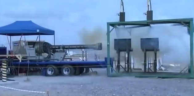

Railgun on the back of flatbed of a truck during testing. Firing through concrete and metal. This if from the General Atomics video


Image of the navy railgun to be deployed in sea trials in 2016. This gun would be reduced in size for a tank killing railgun for a new ground Vehicle


General Atomics has a vision of a mobile ground based railgun system that involves three heavy trucks. BAE would have to reduce the size and weight of a fighting vehicle gun by about ten times.


Railgun ship testing

In 2016, Naval Sea Systems Command will conduct the first at sea test of its electromagnetic railgun, hurling a guided 44 pound projectile and hypersonic speeds off the coast of Florida, NAVSEA officials said on Tuesday.

The BAE Systems designed test weapon will be mounted on the newly delivered Joint High Speed Vessel USNS Trenton (JHSV-5) and taken to Eglin Air Force Base’s maritime test range off the Florida panhandle late in the summer of 2016. The Navy originally planned to use the JHSV USNS Millinocket (JHSV- 3) for the test.

“It’s a naval surface fire support demonstration, the Navy’s first to engage an over the horizon target [with a railgun],” Capt. Mike Ziv, NAVSEA’s program manager directed energy and electronic warfare program office told attendees at the Navy’ League’s Sea-Air-Space 2015 Exposition.


An artist rendering shows the Office of Naval Research-funded electromagnetic railgun installed aboard the joint high-speed vessel USNS Millinocket (JHSV- 3). US Navy Image

Officials expect to fire 20 shots from the EMRG on board Trenton ; the last five are expected to be aimed to hit targets anchored off the coast.


With the EMRG launcher on the flight deck, the rest of the system comprising the control van and pulsed power - housed in four 20-ft ISO shipping containers - will be placed below deck in Trenton 's mission bay. Cables will be routed from the pulsed power up to the gun via an existing flight deck access point. The containers are those used on the test range at the Naval Surface Warfare Center Dahlgren in Virginia, Capt Ziv noted.
The Florida test will place a static floating target at a range of 25 to 50 nautical miles from the test ship and fire five GPS guided hyper velocity projectiles (HVP) at the target as the final part of 20 planned firings for the railgun at the Eglin range.

“It’s an over the horizon engagement. We’re firing on a ballistic trajectory and guiding into intercepting that target,” he said to reporters following the briefing.

“Eventually when we have a little bit more advancement in the projectile there will be some ability to communicate with [the round].”

As the program develops, the Navy is zeroing in on about 10,000-ton sized guided missile cruisers and destroyers as the anticipated platforms to field the weapons.

NAVSEA is currently conducting an in-depth study of including the railgun on the Zumwalt-class (DDG-1000) guided missile destroyers for the first platform for the weapon.
SOURCES - Breaking Defense, Air force, FBO.gov, reuters

Tuesday, April 8, 2014

Railgun

From Wikipedia, the free encyclopedia

Naval Surface Warfare Center test firing in January 2008[1]
A railgun is an electrically powered electromagnetic projectile launcher based on similar principles to the homopolar motor. A railgun comprises a pair of parallel conducting rails, along which a sliding armature is accelerated by the electromagnetic effects of a current that flows down one rail, into the armature and then back along the other rail.[2]
Railguns have long existed as experimental technology but the mass, size and cost of the required power supplies have prevented railguns from becoming practical military weapons. However, in recent years, significant efforts have been made towards their development as feasible military technology. For example, in the late 2000s, the U.S. Navy tested a railgun that accelerates a 3.2 kg (7 pound) projectile to hypersonic velocities of approximately 2.4 kilometres per second (5,400 mph), about Mach 7.[3] They gave the project the Latin motto "Velocitas Eradico", Latin for "I, [who am] speed, eradicate".
In addition to military applications, railguns have been proposed to launch spacecraft into orbit; however, unless the launching track was particularly long, and the acceleration required spread over a much longer time, such launches would necessarily be restricted to unmanned spacecraft.

Basics


Schematic diagram of a railgun
The armature may be an integral part of the projectile, but it may also be configured to accelerate a separate, electrically isolated or non-conducting projectile. Solid, metallic sliding conductors are often the preferred form of railgun armature but "plasma" or "hybrid" armatures can also be used. A plasma armature is formed by an arc of ionised gas that is used to push a solid, non-conducting payload in a similar manner to the propellant gas pressure in a conventional gun. A hybrid armature uses a pair of "plasma" contacts to interface a metallic armature to the gun rails. Solid armatures may also "transition" into hybrid armatures, typically after a particular velocity threshold is exceeded.
In its simplest (and most commonly used) form, the railgun differs from a traditional homopolar motor in that no use is made of additional field coils (or permanent magnets). This configuration is thus a self-excited linear homopolar motor formed by a single loop of current. A relatively common variant of this configuration is the augmented railgun in which the driving current is channelled through additional pairs of parallel conductors, arranged to increase ("augment") the magnetic field experienced by the moving armature.[4] In electric motor terminology, augmented railguns are usually series-wound configurations.
A railgun requires a pulsed, direct current power supply. For potential military applications, railguns are usually of interest because they can achieve much greater muzzle velocities than guns powered by conventional chemical propellants. Increased muzzle velocities can convey the benefits of increased firing ranges while, in terms of target effects, increased terminal velocities can allow the use of kinetic energy rounds as replacements for explosive shells. Therefore, typical military railgun designs aim for muzzle velocities in the range of 2000–3500 m/s with muzzle energies of 5–50 MJ. For single loop railguns, these mission requirements require launch currents of a few million amperes, so a typical railgun power supply might be designed to deliver a launch current of 5 MA for a few milliseconds. As the magnetic field strengths required for such launches will typically be approximately 10 T, most contemporary railgun designs are effectively "air-cored", i.e. they do not use ferromagnetic materials such as iron to enhance the magnetic flux.
It may be noted that railgun velocities generally fall within the range of those achievable by two stage light gas guns; however, the latter are generally only considered to be suitable for laboratory use while railguns are judged to offer some potential prospects for development as military weapons. In some hypervelocity research projects, projectiles are "pre-injected" into railguns, to avoid the need for a standing start, and both two stage light gas guns and conventional powder guns have been used for this role. In principle, if railgun power supply technology can be developed to provide compact, reliable and lightweight units, then the total system volume and mass needed to accommodate such a power supply and its primary fuel can become less than the required total volume and mass for a mission equivalent quantity of conventional propellants and explosive ammunition. Such a development would then convey a further military advantage in that the elimination of explosives from any military weapons platform will decrease its vulnerability to enemy fire.

History


German railgun diagrams
In 1918, French inventor Louis Octave Fauchon-Villeplee invented an electric cannon which is an early form of railgun. He filed for a US patent on 1 April 1919, which was issued in July 1922 as patent no. 1,421,435 "Electric Apparatus for Propelling Projectiles".[5] In his device, two parallel busbars are connected by the wings of a projectile, and the whole apparatus surrounded by a magnetic field. By passing current through busbars and projectile, a force is induced which propels the projectile along the bus-bars and into flight.[6]
In 1944, during World War II, Joachim Hänsler of Germany's Ordnance Office built the first working railgun, and an electric anti-aircraft gun was proposed. By late 1944 enough theory had been worked out to allow the Luftwaffe's Flak Command to issue a specification, which demanded a muzzle velocity of 2,000 m/s (6,600 ft/s) and a projectile containing 0.5 kg (1.1 lb) of explosive. The guns were to be mounted in batteries of six firing twelve rounds per minute, and it was to fit existing 12.8 cm FlaK 40 mounts. It was never built. When details were discovered after the war it aroused much interest and a more detailed study was done, culminating with a 1947 report which concluded that it was theoretically feasible, but that each gun would need enough power to illuminate half of Chicago.[6]
During 1950, Sir Mark Oliphant, an Australian physicist and first director of the Research School of Physical Sciences at the new Australian National University, initiated the design and construction of the world's largest (500 megajoule) homopolar generator.[7] This machine was operational from 1962 and was later used to power a large-scale railgun that was used as a scientific experiment.[8]

Design

Theory

A railgun consists of two parallel metal rails (hence the name) connected to an electrical power supply. When a conductive projectile is inserted between the rails (at the end connected to the power supply), it completes the circuit. Electrons flow from the negative terminal of the power supply up the negative rail, across the projectile, and down the positive rail, back to the power supply.[9]
This current makes the railgun behave as an electromagnet, creating a magnetic field inside the loop formed by the length of the rails up to the position of the armature. In accordance with the right-hand rule, the magnetic field circulates around each conductor. Since the current is in the opposite direction along each rail, the net magnetic field between the rails (B) is directed at right angles to the plane formed by the central axes of the rails and the armature. In combination with the current (I) in the armature, this produces a Lorentz force which accelerates the projectile along the rails, away from the power supply. There are also Lorentz forces acting on the rails and attempting to push them apart, but since the rails are mounted firmly, they cannot move.
By definition, if a current of one ampere flows in a pair of infinitely long parallel conductors that are separated by a distance of one metre, then the magnitude of the force on each metre of those conductors will be exactly 0.2 micro-newtons. Furthermore, in general, the force will be proportional to the square of the magnitude of the current and inversely proportional to the distance between the conductors. It also follows that, for railguns with projectile masses of a few kg and barrel lengths of a few m, very large currents will be required to accelerate projectiles to velocities of the order of 1000 m/s.
A very large power supply, providing on the order of one million amperes of current, will create a tremendous force on the projectile, accelerating it to a speed of many kilometres per second (km/s). 20 km/s has been achieved with small projectiles explosively injected into the railgun. Although these speeds are possible, the heat generated from the propulsion of the object is enough to erode the rails rapidly. Under high-use conditions, current railguns would require frequent replacement of the rails, or to use a heat-resistant material that would be conductive enough to produce the same effect.

Mathematical formula

The magnitude of the force vector can be determined from a form of the Biot–Savart law and a result of the Lorentz force. It can be derived mathematically in terms of the permeability constant (\mu_0), the radius of the rails (which are assumed to be circular in cross section) (r), the distance between the centrepoints of the rails (d) and the current in amps through the system (I) as follows:
It can be shown from the Biot-Savart law that at one end of a semi-infinite current-carrying wire, the magnetic field at a given perpendicular distance (s) from the end of the wire is given by:
\mathbf{B}(s) = \frac{\mu_0 I}{ 2\pi s}
Note this is if the wire runs from the location of the armature e.g. from x = 0 back to  x = -\infty .
So, if the armature connects the ends of two such semi-infinite wires separated by a distance, d, the total field from both wires at any given point on the armature is:
B(s) = \frac{\mu_0 I}{ 2\pi}\left(\frac{1}{s}+\frac{1}{d-s}\right)
To obtain an approximate expression for the average magnetic field on a railgun armature, we assume that the rail radius r is small compared with the rail separation d and, by assuming that the railgun rails can be modelled as a pair of semi-infinite conductors, we compute the following integral:
B_{\text{avg}} = \frac{1}{2d}\int_r^{d-r}B(s)\text{d}s = \frac{\mu_0 I}{ 4\pi d}\int_r^{d-r}\left(\frac{1}{s}+\frac{1}{d-s}\right)\text{d}s=\frac{\mu_0 I}{ 2\pi d} \ln \frac{d-r}{r} \approx \frac{\mu_0 I}{ 2\pi d} \ln \frac{d}{r}
By the Lorentz force law, the magnetic force on a current-carrying wire is given by IdB, so since the width of the conductive projectile is d, we have
F = IdB_{\text{avg}} = \frac{\mu_0 I^2}{ 2\pi}\ln \frac{d}{r}
The formula is based on the assumption that the distance (l) between the point where the force (F) is measured and the beginning of the rails is greater than the separation of the rails (d) by a factor of about 3 or 4 (l>3d). Some other simplifying assumptions have also been made; to describe the force more accurately, the geometry of the rails and the projectile must be considered.
Since it is not easy to produce an electromagnetic expression for the railgun force that is both simple and reasonably accurate, most simple railgun analyses actually used a lumped circuit model to describe the relationship between the driving current and the railgun force. In these models the voltage across the railgun breech is given by:
V = I.R + \frac{\text{d}(L.I)}{\text{d}t}
Then the barrel resistance and inductance are assumed to vary linearly with the projectile position, so that
R = R'.x
L = L'.x
from which
V = I.(R'x + L'v) + L'x\frac{\text{d}I}{\text{d}t}
If the driving current is held constant, there is a power flow equal to I^2L'v which represents the electromagnetic work done. In this simple model, exactly half of this is assumed to be needed to establish the magnetic field along the barrel, i.e. as the length of the current loop increases. The other half represents the power flow into the kinetic energy of the projectile. Since power can be expressed as force times speed, this gives the standard result that the force on the railgun armature is given by:
F = \frac{L'I^2}{2}
This simple equation shows that high accelerations will require very high currents. For an ideal square bore railgun, the value of L' would be about 0.6 microHenries per metre (\mu.H/m) but most practical railgun barrels exhibit lower values of L' than this.
Since the lumped circuit model describes the railgun force in terms of fairly normal circuit equations, it becomes possible to specify a simple time domain model of a railgun.
Ignoring friction and air drag, the projectile acceleration is given by:
\frac{\text{d}v}{\text{d}t} = \frac{L'I^2}{2m}
where m is the projectile mass. The motion along the barrel is given by:
\frac{\text{d}x}{\text{d}t} = v
and the above voltage and current terms can be placed into appropriate circuit equations to determine the time variation of current and voltage.

Considerations

The power supply must be able to deliver large currents, sustained and controlled over a useful amount of time. The most important gauge of power supply effectiveness is the energy it can deliver. As of December 2010, the greatest known energy used to propel a projectile from a railgun was 33 megajoules.[10] The most common forms of power supplies used in railguns are capacitors and compulsators which are slowly charged from other continuous energy sources.
The rails need to withstand enormous repulsive forces during shooting, and these forces will tend to push them apart and away from the projectile. As rail/projectile clearances increase, arcing develops, which causes rapid vaporization and extensive damage to the rail surfaces and the insulator surfaces. This limited some early research railguns to one shot per service interval.
The inductance and resistance of the rails and power supply limit the efficiency of a railgun design. Currently different rail shapes and railgun configurations are being tested, most notably by the United States Navy, the Institute for Advanced Technology, and BAE Systems.

Materials used

The rails and projectiles must be built from strong conductive materials; the rails need to survive the violence of an accelerating projectile, and heating due to the large currents and friction involved. Some erroneous work has suggested that the recoil force in railguns can be redirected or eliminated; careful theoretical and experimental analysis reveals that the recoil force acts on the breach closure just as in a chemical firearm.[11][12][13][14] The rails also repel themselves via a sideways force caused by the rails being pushed by the magnetic field, just as the projectile is. The rails need to survive this without bending and must be very securely mounted.

Heat dissipation

Massive amounts of heat are created by the electricity flowing through the rails, as well as by the friction of the projectile leaving the device. The heat created by this friction itself can cause thermal expansion of the rails and projectile, further increasing the frictional heat. This causes three main problems: melting of equipment, decreased safety of personnel, and detection by enemy forces. As briefly discussed above, the stresses involved in firing this sort of device require an extremely heat-resistant material. Otherwise the rails, barrel, and all equipment attached would melt or be irreparably damaged.
In practice the rails are, with most designs of railgun, subject to erosion due to each launch; in addition, projectiles can be subject to some degree of ablation, and this can limit railgun life, in some cases severely.[15]

Applications

Railguns have a number of potential practical applications, primarily for the military. However, there are other theoretical applications currently being researched.

Launch or launch assist of spacecraft

Electrodynamic assistance to launch rockets has been studied.[16] Space applications of this technology would likely involve specially formed electromagnetic coils and superconducting magnets.[17] Composite materials would likely be used for this application.[18]
For space launches from Earth, relatively short acceleration distances (less than a few km) would require very strong acceleration forces, higher than humans can tolerate. Other designs include a longer helical (spiral) track, or a large ring design whereby a space vehicle would circle the ring numerous times, gradually gaining speed, before being released into a launch corridor leading skyward.
Key Parameters[19] Value Units
Muzzle Velocity 7500 m/s
Muzzle Energy 35 GJ
Launcher length 1600 m
Maximum acceleration 19500 m/s^2
Maximum acceleration 1988 g's
Launch time 0.43 s
Current density 6.8 MA/m
In 2003, Ian McNab outlined a plan to turn this idea into a realized technology.[19] The accelerations involved are significantly stronger than human beings can handle. This system would only be used to launch sturdy materials, such as food, water, and fuel. Note that escape velocity under ideal circumstances (equator, mountain, heading east) is 10.735 km/s. The system would cost $528/kg, compared with $20,000/kg[19] on the space shuttle (see Non-rocket spacelaunch). The railgun system McNab suggested would launch 500 tons per year, spread over approximately 2000 launches per year. Because the launch track would be 1.6 km, power will be supplied by a distributed network of 100 rotating machines (compulsator) spread along the track. Each machine would have a 3.3 ton carbon fibre rotor spinning at high speeds. A machine can recharge in a matter of hours using 10 MW. This machine could be supplied by a dedicated generator. The total launch package would weigh almost 1.4 tons. Payload per launch in these conditions is over 400 kg.[19] There would be a peak operating magnetic field of 5T – Half of this coming from the rails, and the other half from augmenting magnets. This halves the required current through the rails, which reduces the power fourfold.

Weaponry


Drawings of electric gun projectiles
Railguns are being researched as weapons with projectiles that do not contain explosives or propellants, but are given extremely high velocities: 3,500 m/s (11,500 ft/s) (approximately Mach 10 at sea level) or more (for comparison, the M16 rifle has a muzzle speed of 930 m/s (3,050 ft/s), and the 16"/50 caliber Mark 7 gun that armed World War II American battleships has a muzzle speed of 760 m/s (2,490 ft/s)), which would make their kinetic energy equal or far superior to the energy yield of an explosive-filled shell of greater mass. This would decrease ammunition size and weight, allowing more ammunition to be carried and eliminating the hazards of carrying explosives or propellants in a tank or naval weapons platform. Also, by firing at greater velocities, railguns have greater range, less bullet drop, less time to target, and less wind drift, bypassing the physical limitations of conventional firearms: "the limits of gas expansion prohibit launching an unassisted projectile to velocities greater than about 1.5 km/s and ranges of more than 50 miles [80 km] from a practical conventional gun system."[20]
The increased launch velocities of railguns would also allow greater capability for both offensive and defensive applications as compared to traditional weapons. The greater kinetic energy and decreased time on target associated with increased launch velocities, when coupled with non-traditional rounds, would allow a single railgun to effectively attack both airborne and land or sea based targets.
If it were possible to apply the technology as a rapid-fire automatic weapon, a railgun would have further advantages of increased rate of fire. The feed mechanisms of a conventional firearm must move to accommodate the propellant charge as well as the ammunition round, while a railgun would only need to accommodate the projectile. Furthermore, a railgun would not have to extract a spent cartridge case from the breech, meaning that a fresh round could be cycled almost immediately after the previous round has been shot.
Many critics of weaponized railgun systems claim running at a suitable exit velocity and rate of fire would consume too much power, though this would likely not be a problem for nuclear-powered systems such as on large warships or submarines.
The first weaponized railgun planned for production, the General Atomics Blitzer system, began full system testing in September 2010. The weapon launches a streamlined discarding sabot round designed by Boeing's Phantom Works at 1,600 m/s (5,200 ft/s) (approximately Mach 5) with accelerations exceeding 60,000 g.[21] During one of the tests, the projectile was able to travel an additional 7 kilometres (4.3 mi) downrange after penetrating a 18 inch (3.2 mm) thick steel plate. The company hopes to have an integrated demo of the system by 2016 followed by production by 2019, pending funding. Thus far, the project is self-funded.[22]
In October 2013, General Atomics unveiled a land based version of the Blitzer railgun. A company official claimed the gun could be ready for production in "two to three years".[23]
The U.S. Navy plans to integrate a railgun that has a range of 100 mi (160 km) onto a ship by 2016.[24] By that time the Navy expects to have a weapon that can fire multiple projectiles per minute. The hyper-velocity rounds weigh 23 lb (10 kg) and cost about $25,000 each. They have command guidance but are planned to be self-guided in the future.[25] Currently the only ships that can produce enough electrical power to get desired performance are the Zumwalt-class destroyers; they can generate 78 megawatts of power, far more than would be necessary. Engineers are working to derive technologies from the DDG-1000 series ships into a battery system to store enough energy so other warships can operate a railgun.[26] Even if current ships, such as the Arleigh Burke-class destroyer, can be upgraded with enough power to operate a railgun, the space taken up on the ships by the integration of an additional weapon system may force the removal of existing weapon systems to make room available.[27] The first shipboard tests will be from a railgun installed on a Joint High Speed Vessel. Though ships of that class are non-combatants, they were chosen for their available cargo and topside space and schedule flexibility. They will not be permanently installed on the JHSV and the Navy has yet to decide which ship classes will receive a fully-operational railgun.[28]

Tests


Diagram showing the cross-section of a linear motor cannon
Full-scale models have been built and fired, including a 90 mm (3.5 in) bore, 9 MJ kinetic energy gun developed by the US DARPA. Rail and insulator wear problems still need to be solved before railguns can start to replace conventional weapons. Probably the oldest consistently successful system was built by the UK's Defence Research Agency at Dundrennan Range in Kirkcudbright, Scotland. This system has now been operational for over 10 years at an associated flight range for internal, intermediate, external and terminal ballistics, and achieved several mass and velocity records.[citation needed]
The Yugoslavian Military Technology Institute developed, within a project named EDO-0, a railgun with 7 kJ kinetic energy, in 1985. In 1987 a successor was created, project EDO-1, that used projectile with a mass of 0.7 kg (1.5 lb) and achieved speeds of 3,000 m/s (9,800 ft/s), and with a mass of 1.1 kg (2.4 lb) reached speeds of 2,400 m/s (7,900 ft/s). It used a track length of 0.7 m (2.3 ft). According to those working on it, with other modifications it was able to achieve a speed of 4,500 m/s (14,800 ft/s). The aim was to achieve projectile speed of 7,000 m/s (23,000 ft/s). At the time, it was considered a military secret.[citation needed]
The United States military is funding railgun experiments. At the University of Texas at Austin Centre for Electromechanics, military railguns capable of delivering tungsten armor piercing bullets with kinetic energies of nine megajoules have been developed.[29] 9 MJ is enough energy to deliver 2 kg (4.4 lb) of projectile at 3 km/s (1.9 mi/s) – at that velocity a rod of tungsten or another dense metal could easily penetrate a tank, and potentially pass through it.
The United States Naval Surface Warfare Center Dahlgren Division demonstrated an 8 MJ railgun firing 3.2 kg (7.1 lb) projectiles in October 2006 as a prototype of a 64 MJ weapon to be deployed aboard Navy warships. The main problem the U.S. Navy has had with implementing a railgun cannon system is that the guns wear out due to the immense heat produced by firing. Such weapons are expected to be powerful enough to do a little more damage than a BGM-109 Tomahawk missile at a fraction of the projectile cost.[30] Since then, BAE Systems has delivered a 32 MJ prototype to the U.S. Navy.[31]
On January 31, 2008 the US Navy tested a railgun that fired a shell at 10.64 MJ with a muzzle velocity of 2,520 m/s (8,270 ft/s).[32] Its expected performance is a muzzle velocity over 5,800 m/s (19,000 ft/s), accurate enough to hit a 5-metre (16 ft) target over 200 nmi (370 km) away while firing at 10 shots per minute. The power was provided by a new 9-megajoule prototype capacitor bank using solid-state switches and high-energy-density capacitors delivered in 2007 and an older 32-MJ pulse power system from the US Army’s Green Farm Electric Gun Research and Development Facility developed in the late 1980s that was previously refurbished by General Atomics Electromagnetic Systems (EMS) Division.[33] It is expected to be ready between 2020 to 2025.[34]
A test of a railgun took place on December 10, 2010, by the US Navy at the Naval Surface Warfare Center Dahlgren Division.[35] During the test, the Office of Naval Research set a world record by conducting a 33 MJ shot from the railgun, which was built by BAE Systems.[36][37]
A more recent test took place in February, 2012, at the Naval Surface Warfare Center Dahlgren Division. While similar in energy to the aforementioned test, the railgun used is considerably more compact, with a more conventional looking barrel.[38] A General Atomics-built prototype was delivered for testing in October 2012.[39]
External video
Official 33MJ video
Additional footage
February 2012 test

Trigger for inertial confinement fusion

Railguns may also be miniaturized for inertial confinement nuclear fusion.
  • Fusion is triggered by very high temperature and pressure at the core.
    • Current technology calls for multiple lasers, usually over 100, to concurrently strike a fuel pellet, creating a symmetrical compressive pressure.
    • Railguns may be able to trigger fusion by firing energetic plasma from multiple directions. The process developed involves four key steps.[40]
      • Plasma is pumped into a chamber.
      • When the pressure is great enough, a diaphragm will rupture, sending gas down the rail.
      • Shortly afterwards, a sufficient voltage is applied to the rails, creating a conduction path of ionized gas.
      • This plasma accelerated down the rail, eventually being ejected at a large velocity.
  • The rails and dimensions are on the order of centimetres.

See also