From Wikipedia, the free encyclopedia
| J58 | |
|---|---|
 |
|
| J58 engine on display at the Evergreen Aviation & Space Museum | |
| Type | Turbojet |
| Manufacturer | Pratt & Whitney |
| First run | 1958 |
| Major applications | Lockheed A-12 Lockheed SR-71 |
Contents
Design and development
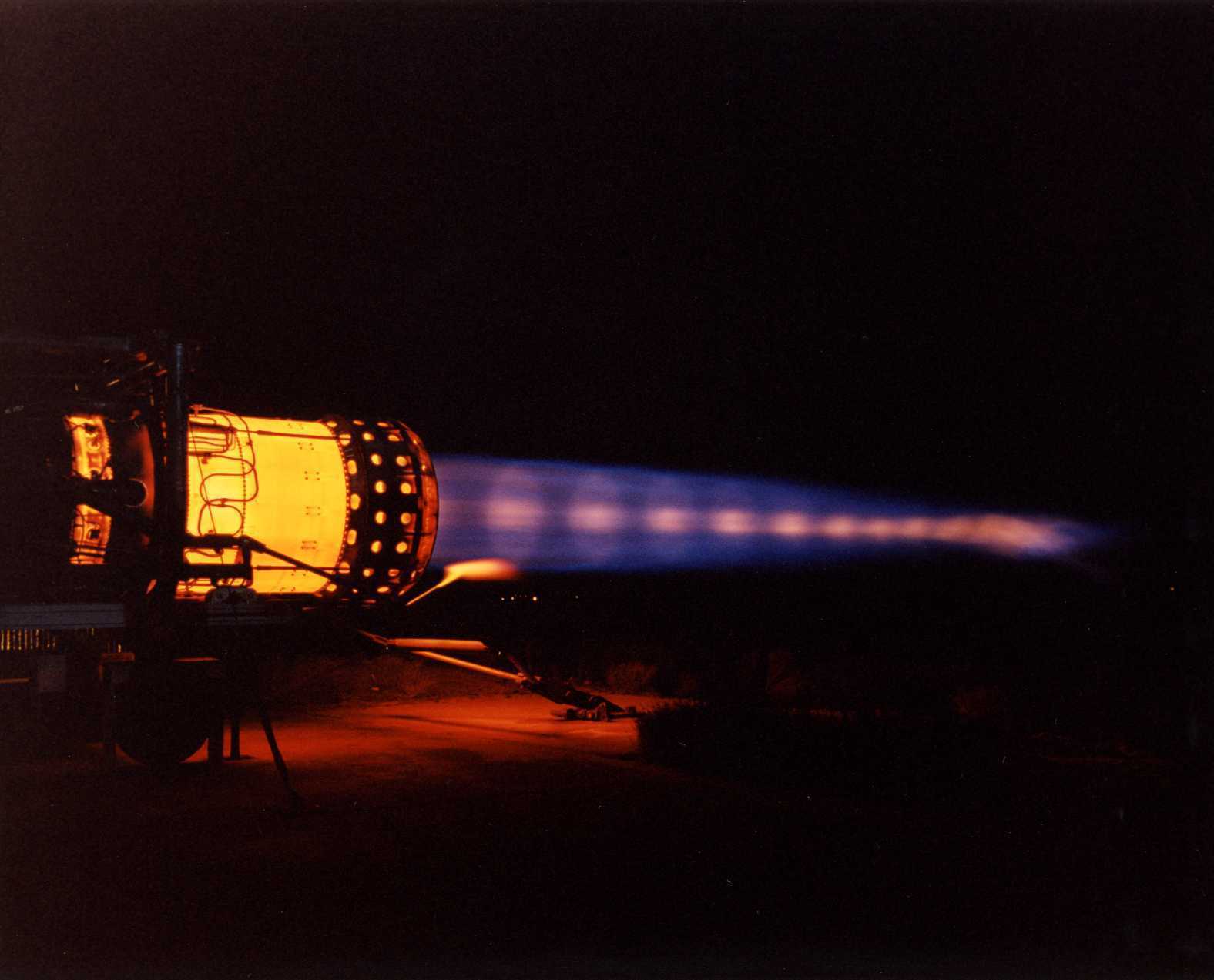
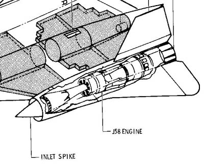
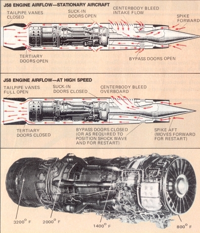
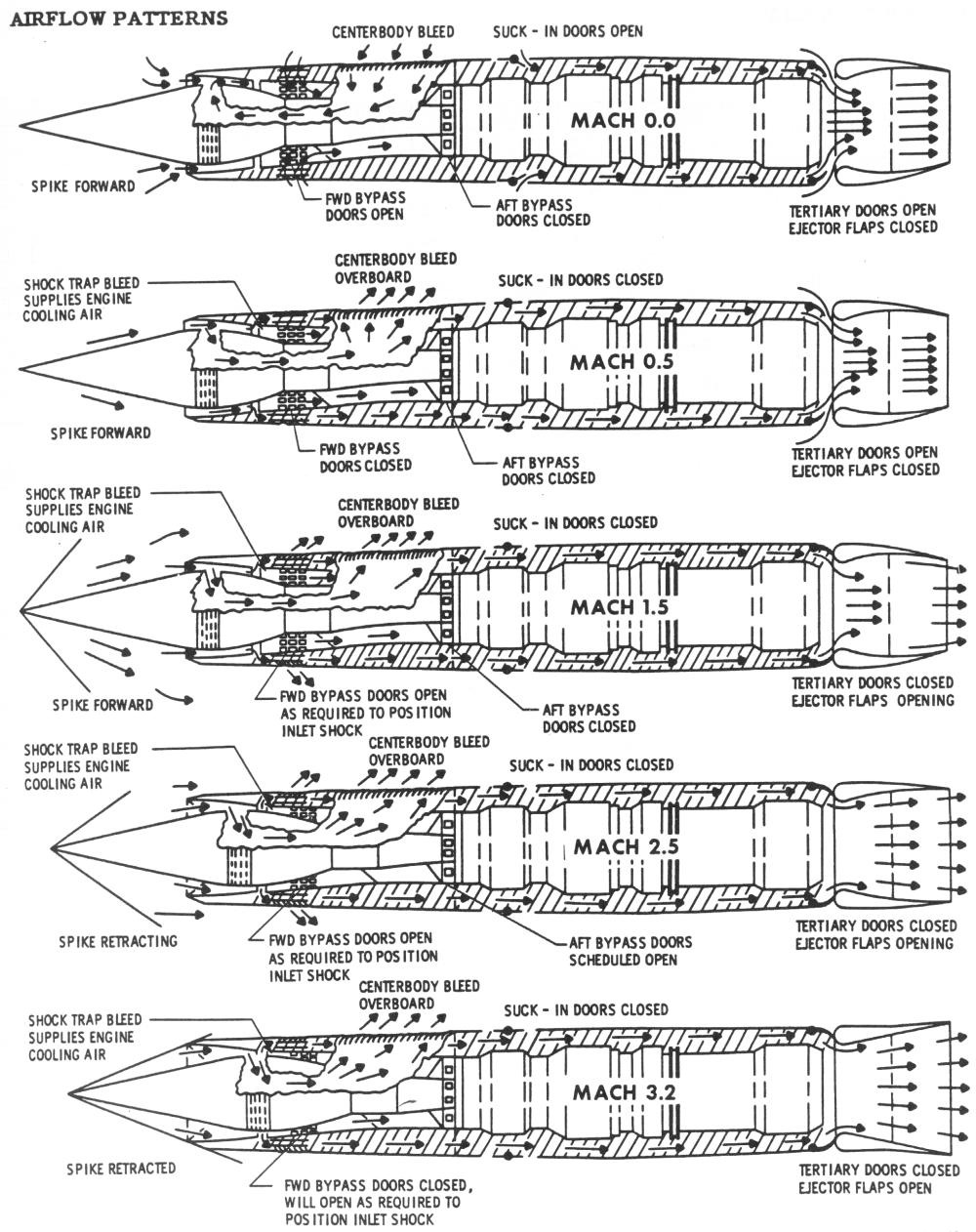
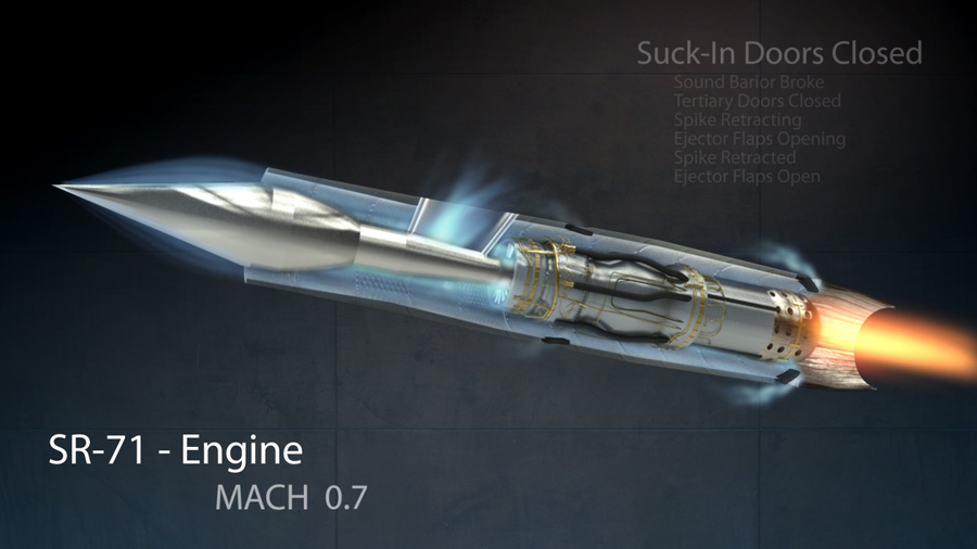
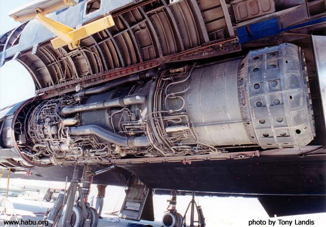
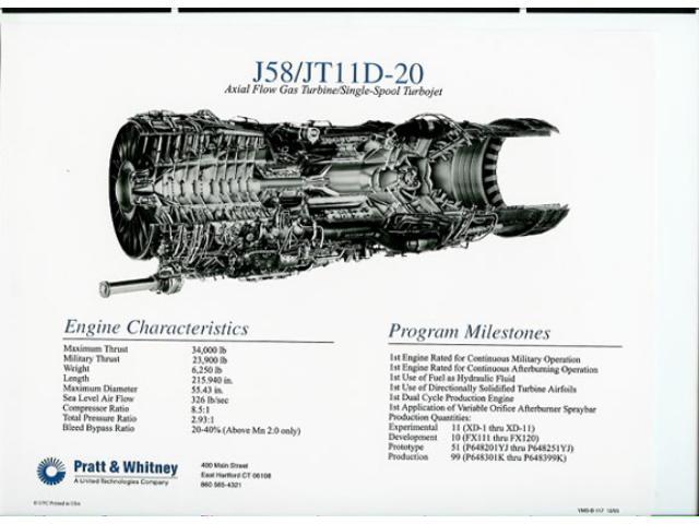
The J58 was initially developed for the US Navy to power the planned version[clarification needed] of the Martin P6M jet flying boat.[2][dead link] Upon cancellation of this aircraft, it was selected by Convair and Lockheed for their supersonic projects.[clarification needed] Other sources link its origin to the USAF's requirement for a powerplant for the WS-110A, the future XB-70 Valkyrie.[3] The J-58 produced 32,000 lbf (142 kN) of thrust. It was the first engine to be able to operate on afterburner for extended periods of time, and the first engine to be flight-qualified by the United States Air Force for Mach 3. A major feature of the J58 installation were the conical spikes in the variable-geometry inlets, which automatically moved fore and aft, controlled by an Air Inlet Computer. The spike altered the flow of supersonic air, ensuring good pressure recovery and minimum distortion at the engine inlet. The conical spikes are locked in the forward position below 30,000 feet and un-locked above that altitude. Above Mach 1.6 they are retracted approximately 1⅝ inch (4 cm ) per Mach 0.1, up to total of about 26 inches (66 cm).
The engine's high operating speeds and temperatures required a new jet fuel, JP-7. Its reluctance to be ignited required triethylborane (TEB) to be injected into the engine to ignite it, and to ignite the afterburner in flight; above -5 °C TEB spontaneously ignites in contact with air. Each engine carried a nitrogen-pressurized sealed tank with 600 cm3 (20.7 ounces) of TEB, sufficient for at least 16 starts, restarts, or afterburner lights; this number was one of the limiting factors of SR-71 endurance, as after each air refueling the afterburners had to be reignited.[4] When the pilot moved the throttle from cut-off to idle position, fuel flowed into the engine, and shortly afterwards an approx. 50 cm3 (1.7 ounce) shot of TEB was injected into the combustion chamber, where it spontaneously ignited and lit the fuel with a green flash. In some conditions, however, the TEB flow was obstructed by coking deposits on the injector nozzle, hindering restart attempts. Refilling the TEB tank was a perilous task; the maintenance crew wore silver fire suits.[5] Conversely, the JP-7 fueling was so safe that some aircraft maintenance was permitted during filling. The chemical ignition was chosen instead of a conventional igniter for reliability reasons, and to reduce mechanical complexity. The TEB tank is cooled with fuel flowing around it, and contains a disk that ruptures in case of overpressure, allowing TEB and nitrogen to discharge into the afterburner.
The fuel flowing into the engine is used as a coolant to cool the engine, hydraulic fluid, oil, TEB tank, afterburner nozzle actuator control lines, air conditioning systems, and the parts of the airframe subjected to aerodynamic heating.
The engine lubricant was a silicone-based grease. It was solid at room temperature, and was preheated prior to engine start.
Modifications for Mach 3.2 flight
Introduction
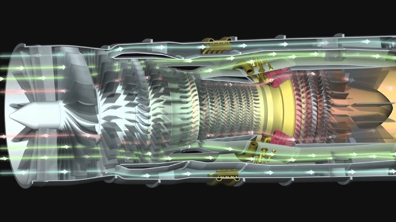
Jet engines take in their air at about Mach 0.4 irrespective of their flight speed, whether it be zero or Mach 3. Efficient operation of the engine inlet requires that it delivers the air to the engine at that speed.[6] The Lockheed Blackbird family of aircraft was designed to travel at speeds over Mach 3.2 and the slowing down of the air from this high speed to about Mach 0.4 was controlled by the intake shock cone and the shape of the downstream internal ducting(both were part of the airframe and designed by Lockheed). As air slows down, its temperature rises (to nearly 400 deg C at a flight speed of Mach 3.2) and it was this high temperature entering the compressor that prevented the J58, as originally designed, from powering the Blackbirds to Mach 3.2.[7][8] This section describes how the compressor was modified for Mach 3.2 flight to handle the aerodynamic effects of high inlet temperature. The section is based on information in U.S.Patent 3,344,606 and the SR-71 Flight Manual.[9][10]Modifications to the J58 compressor
The patent summarizes why the J58 would not work at Mach 3.2 - "As a result of the ram air temperature rise the thrust output drops because of insufficient airflow, compressor tolerance to surge (or compressor stall) is poor, and low compressor efficiency occurs resulting in high fuel consumption. Also the compressor blades are subjected to high stress from the combination of high rotational speed and flutter from rotating stall in the front stages".[9]It specifies the object of the invention - "to improve the thrust generating quality of a turbojet engine with afterburner during high supersonic flight speed operation and to improve the compressor efficiency, the compressor surge margin and the compressor blade and vane fatigue problem".[9]
It summarizes the solution - ".. by bleeding a portion of the compressor air from an intermediate compressor stage and recovering the air in the afterburner for reheating therein prior to discharge to atmosphere with the remainder of the exhaust gasses".[9]
It was found that 20% of the engine flow needed to be bled from the fourth stage to combat the effects of high compressor inlet temperature and to restore the operation of the compressor to an acceptably high efficiency and flow capacity when operating at Mach 3.2.[11]
The bleed air was returned to the engine to provide both cooling for the afterburner liner and more air for afterburner combustion.[11] It passed through six external tubes from the compressor to the afterburner.
The SR-71 Flight Manual provides information on the use of the bleed ("bleed and IGV shift schedule")[7] in terms of engine RPM and Mach number or compressor inlet temperature. It shows that this air bleed, which it calls internal, is also necessary, together with an extra bleed, which it calls external, during starting and low engine RPM.[11]
The schedule shows that variable inlet guide vanes (IGV) were also part of the compressor design. Unlike most variable IGV, where the whole vane pivots,[12] the J58 vanes had 2-position, part-span trailing edge flaps only.[11]
Like the bleed flow, the position of the flaps was also determined by the engine speed and compressor inlet temperature.[7]
A schematic view of the engine is also shown on the schedule showing the engine bleed air path from the compressor to the afterburner.[7]
Final configuration
The final configuration of the J58 for Mach 3.2 flight was that of a "turbojet with bleed air recovery", as stated in the patent. An alternative classification was a "turbojet with afterburner and compressor bleed bypass at high Mach", as stated in the Flight Manual. The engine designation was JT11-D20.[11]Contemporary solutions for flight at Mach 3
Alternative solutions to combat the adverse effects of high inlet temperature on the aerodynamic performance of the compressor were rejected by the patentee and are listed in the patent. One of those solutione was,however, used in a contemporary installation. The GE YJ93/XB-70 used a variable stator compressor to avoid front stage stall and rear stage choking.[13] Another possible solution,pre-compressor cooling, was used on the MIG-25. Water/methanol was injected from a spray mast in front of the compressor to lower the intake temperature for short durations at maximum speed,.[14] Pre-compressor cooling was also proposed for a Mach 3 reconnaissance Phantom[15] and the Mach 3+ F-106 RASCAL project[16]The complete engine installation or propulsion system

Introduction
The propulsion system consisted of the intake, engine, nacelle or secondary airflow and ejector nozzle(propelling nozzle).[17] The propulsive thrust distribution between these components changed with flight speed.at Mach 2.2 inlet 13% - engine 73% - ejector 14%
at Mach 3.0+ inlet 54% - engine 17.6% - ejector 28.4%[17]
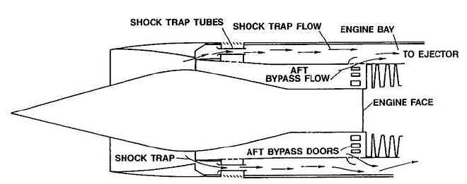
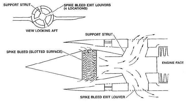
Intake
The intake had to supply air to the engine with minimum pressure loss and distortion and at the speed dictated by the engine, namely about Mach 0.4.[6] It had to do this at all flight conditions.Nacelle airflow and ejector nozzle
The ejector nozzle, together with the engine variable nozzle, performed the reverse function of the inlet accelerating the turbine exhaust from about Mach 0.4 back up to Mach 3.[18] Mach 3 exhaust velocity is higher than Mach 3 flight velocity due to the much higher temperature in the exhaust. The nacelle airflow from the intake controlled the expansion of the hot engine exhaust in the ejector nozzle.[19] This air flowed around the engine and served also to cool the hot external parts of the engine and to purge any combustible mixtures in the event of a fuel or oil leak in the nacelle.Applications
Specification of J58-P-4

Data from [20]
General characteristics
- Type: afterburning turbojet with compressor bleed bypass
- Length: 17 ft 10 in (5.44 m) (an additional 6 in (15 cm) at max. temp.)
- Diameter: 4 ft 9 in (1.45 m)
- Dry weight: approx. 6,000 lb (2,700 kg)
Components
- Compressor: 9-stage, axial flow, single spool
- Combustors: 8 can, annular
- Turbine: two-stage axial flow
- Fuel type: JP-7
Performance
- Maximum thrust: 34,000 pounds-force (150 kN) wet, 25,000 pounds-force (110 kN) dry
- Overall pressure ratio: 6[21]
- Specific fuel consumption: 1.9 lb/(lbf·h) (54 g/(kN·s)) wet, 0.9 lb/(lbf·h) (25 g/(kN·s)) dry
- Thrust-to-weight ratio: approx. 6
- Core air flow: 450 lb/s, (200 kg/s)
See also
- Comparable engines
- General Electric GE4
- General Electric YJ93
- Rolls-Royce/Snecma Olympus 593
- Kuznetsov NK-321
- Tumansky R-15
- Reaction Engines SABRE
- Related lists


Adaptive Versatile Engine Technology
From Wikipedia, the free encyclopedia

Cut-away view of a prospective ADVENT engine
Objective
The objective of ADVENT is to develop an engine that is optimized for several design points, rather than the traditional single point. Instead of having an engine that is designed solely for high speed (like many current fighter engines are) or for high fuel efficiency (like many current commercial engines are), the final ADVENT engine would be designed to operate at both those conditions.[1] Specific goals include reducing average fuel consumption by 25% and reducing the temperature of cooling air produced by the engine.[2]Applications
The ADVENT engine was originally targeted at the Air Force's 2018 Next-Generation Bomber, but uncertainty in that program has led Rolls-Royce (RR), one of the primary developers involved with the project, to predict that the ADVENT engine will be better suited for a potential 2020 engine upgrade for the F-35 Lightning II. RR, who is partnered with GE Aviation on the embattled F136 alternate engine for the F-35, has suggested that the ADVENT development contracts are all the more reason to continue the F136, as any engine upgrade from Pratt & Whitney (makers of the F135 engine currently used in the F-35) would have to be separately funded, either internally or to additional government cost.[3]History
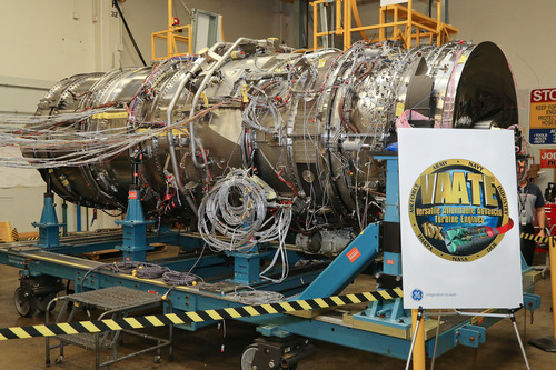
The ADVENT program is one of several related development projects being pursued under the Air Force's Versatile Affordable Advanced Turbine Engines (VAATE) program. After being announced in April 2007, Rolls-Royce and GE Aviation were awarded Phase I contracts in August 2007 to explore concepts, develop and test critical components, and begin preliminary designs of an engine.[1][4]In October 2009, Rolls-Royce was awarded the Phase II contract to continue component testing and integrate the developed technologies into a technology demonstrator engine.[2] GE Aviation was also awarded funds to continue development of their technology demonstration core, which was unexpected as the ADVENT program had originally called for a single contractor to be selected for Phase II.[5]
USAF officials have denied that the program is an attempt to create a backup engine program for the F-35.[6]
With the threat of the GE/RR F136, Pratt & Whitney has funded an adaptive fan variant of its F135, that may qualify for the follow-on Adaptive Engine Technology Development (AETD) program under the US Air Force Research Laboratory.[7]
In 2012, GE was chosen to continue its ADVENT work into the AETD program.[8] Pratt & Whitney was selected over Rolls Royce and GE to continue the AETD program to mature fuel-efficient, high-thrust powerplants.[9]
Operational testing of the engine is expected to begin in 2013.[2]
In 2014, Chuck Hagel requested a $1 billion investment in the engine technology.[10]
General Electric YF120
From Wikipedia, the free encyclopedia
| YF120 | |
|---|---|
| Type | Variable Cycle Turbofan |
| National origin | United States |
| Manufacturer | General Electric |
| First run | 1980s |
| Major applications | Lockheed YF-22 Northrop YF-23 |
| Developed into | General Electric/Rolls-Royce F136 |
Contents
[hide]Development and Design
General Electric began developing the YF120 for the ATF competition in the early 1980s. Unlike competitor Pratt & Whitney, GE elected against developing a conventional low bypass turbofan and instead chose to design a variable cycle engine. This decision was made as a result of the challenging ATF requirement of supercruise. This meant the engine had to produce a large amount of dry thrust (without afterburner) and therefore have high off-design efficiency ("design" being standard cruise conditions).[1]The core technology used in the YF120 was developed during two industry-government programs, the Advanced Technology Engine Gas Generator (ATEGG) and Joint Technology Demonstration Engine (JTDE) programs.[2]
Variable Cycle
The YF120's variable cycle system worked by varying the bypass ratio of engine for different flight regimes, allowing the engine act like either a low bypass turbofan or nearly a turbojet.[1] As a low bypass turbofan (like competitor F119), the engine performed similar to comparable engines. When needed, however, the engine could direct more airflow through the hot core of the engine (like a turbojet), increasing the specific thrust of the engine. This made the engine more efficient at high altitude, high thrust levels than a traditional low bypass turbofan.[3]An expected disadvantage of this variable cycle system would be increased complexity and weight. GE claims to have combated this by using simple pressure driven valves rather than complex mechanically actuated valves to divert airflow. GE stated that this system resulted in the variable cycle system adding only 10 lb to the engine.[1] Additionally a production F120 engine was expected to have 40% fewer parts than the F110 engine.[2]
Thrust Vectoring
The YF120 engine featured a two-dimensional thrust vectoring nozzle. The nozzle allowed for vectoring in the pitch direction. This capability gave the aircraft it was installed in a serious advantage in pitch agility by greatly increasing the amount of nose pitching moment available to the aircraft. The pitching moment is traditionally generated by the horizontal stabilizer (and/or canard, if applicable), but with a thrust vectoring nozzle that moment can be augmented by the thrust of the engine.[citation needed]While the YF120 engine never went into production, it was installed in the YF-22 used for the high angle of attack demonstration program as part of the ATF competition. During this demonstration, the YF120 powered aircraft flew, trimmed, at 60 degrees angle of attack at 82 knots. At this attitude the aircraft was able to demonstrate controlibility. Later analysis revealed that the aircraft could have maintained controlled, trimmed flight up to 70 degrees angle of attack.[4]
Advanced Development
The YF120 was also proposed as the basis for a more exotic engine, the Turbine-Based Combined Cycle (TBCC) engine that was to be used in demonstrator aircraft like the X-43B and future hypersonic aircraft. Specifically, the YF120 was to be the basis for the Revolutionary Turbine Accelerator (RTA-1). The variable cycle technology used in the YF120 would be extended to not only turn the engine into a turbojet but also into a ramjet. In that mode all airflow would bypass the core and be diverted into the afterburner-like "hyperburner" where it would be combusted like a ramjet. This proposed engine was to accelerate from 0 to Mach 4.1 (at 56,000 ft) in eight minutes.[5][6]Applications
Specifications (YF120)
General characteristics
- Type: Twin-Spool, Augmented Turbofan
- Length: 4,242 mm
- Diameter: 1,067 mm
- Dry weight: 1,860 kg
Components
- Compressor: Two stage fan, five stage high pressure compressor (estimated[2])
- Combustors: Annular Combustor
- Turbine: Single stage HPT, Counter-Rotating Single Stage LPT [7]
- Nozzle: Two Dimensional Vectoring Convergent/Divergent
- Fuel type: JP-4 or JP-8
Performance
- Maximum thrust: 35,000 lbf (160 kN) - class
- Power-to-weight ratio:
Variable cycle engine
From Wikipedia, the free encyclopedia
The next generation of Supersonic transport (SST) may require some form of VCE. SST engines require a high Specific Thrust (net thrust/airflow) at supersonic cruise to keep the cross-sectional area of the powerplant to a minimum, so as to reduce aircraft drag. Unfortunately, this implies a high jet velocity not only at supersonic cruise, but at take-off, which makes the aircraft noisy.
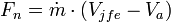
A high specific thrust engine has a high jet velocity by definition, as the following approximate equation for net thrust implies:[1]
where:
 intake mass flow rate
 fully expanded jet velocity (in the exhaust plume)
 aircraft flight velocity
Rearranging the above equation, specific thrust is given by:

So for zero flight velocity, specific thrust is directly proportional to jet velocity.
The Olympus 593 engines in Concorde had a high specific thrust in supersonic cruise and at dry take-off power. This alone would have made the engines noisy, but the problem was compounded by the need for a modest amount of afterburning (reheat) at take-off (and Transonic Acceleration). An SST VCE would have to increase the engine airflow substantially at take-off, to reduce the jet velocity at a given thrust (i.e. a lower specific thrust)
Examples
One SST VCE concept is the Tandem Fan engine. The engine has two fans, both mounted on the low-pressure shaft, with a significant axial gap between the units. In normal flight, the engine is in the series mode, with the flow leaving the front fan passing directly into the second fan, the engine behaving much like a normal turbofan. However, for take-off, climb-out, final-descent and approach, the front fan is allowed to discharge directly through an auxiliary nozzle on the underside of the powerplant nacelle. Auxiliary intakes are opened on each side of the powerplant, allowing air to enter the rear fan and progress through the rest of the engine. Operating the fans in this parallel mode substantially increases the total airflow of the engine at a thrust, resulting in a lower jet velocity and a quieter engine. Back in the 1970s, Boeing modified a Pratt & Whitney JT8D to a Tandem Fan configuration and successfully demonstrated the switch from series to parallel operation (and vice versa) with the engine running, albeit at part power.In the Mid Tandem Fan concept, a high specific flow single stage fan is located between the high pressure (HP) and low pressure (LP) compressors of a turbojet core. Only bypass air is allowed to pass through the fan, the LP compressor exit flow passing through special passages within the fan disc, directly underneath the fan rotor blades. Some of the bypass air enters the engine via an auxiliary intake. During take-off and approach the engine behaves much like a normal civil turbofan, with an acceptable jet noise level (i.e., low specific thrust). However, for supersonic cruise, the fan variable inlet guide vanes and auxiliary intake close-off to minimize bypass flow and increase specific thrust. In this mode the engine acts more like a 'leaky' turbojet (e.g. the F404).
In the Mixed-Flow Turbofan with Ejector concept, a low bypass ratio engine is mounted in front of a long tube, called an ejector. This silencer device is deployed during take-off and approach. Turbofan exhaust gases induce additional air into the ejector via an auxiliary air intake, thereby reducing the specific thrust/mean jet velocity of the final exhaust. The mixed-flow design does not have the advantages of the mid-tandem fan design in terms of low-speed efficiency, but is considerably simpler.
Other Applications
Another application that could benefit from the VCE approach is combat aircraft. Designers normally have to make a compromise on specific thrust of the engine. If they choose a high specific thrust, the reheat specific fuel consumption (SFC) will be very good, but the dry SFC poor. A high specific thrust implies a high fan pressure ratio, which indicates a high nozzle temperature in dry power. Consequently the thrust boost in reheat is relatively low. By definition, both the dry and reheat thrust levels are good.The opposite is true for a low specific thrust engine- i.e. poor reheat SFC, good dry and throttled SFC, good reheat thrust boost and, by definition, low dry and reheated thrust.
A high specific thrust engine would favour an aircraft requiring good duration in reheated combat, but it would be penalised on the range available in dry power.
On the other hand, a low specific thrust engine, would favour an aircraft with the need for long range in dry power, but compromise the time spent in reheated combat.
Thus engine designers often have to make a compromise on engine specific thrust.
However, the ideal Combat VCE would have the high reheat thrust/good reheat SFC associated with a high specific thrust engine, but would have the low SFC of a low specific thrust engine in dry power and throttled back. Devising such an engine is difficult. However, General Electric did develop a Variable Cycle Engine, known as the GE37 or General Electric YF120, for the YF22/YF23 fighter aircraft competition, back in the late 80's. GE used a Double Bypass/Hybrid Fan arrangement, but to date has never disclosed precisely how they exploited the concept. Although the YF120 was a good (possibly better) engine in the fly-off, the USAF erred on the side of caution and selected the more conventional Pratt & Whitney F119 as the powerplant for the production F22.
Advanced Affordable Turbine Engine
From Wikipedia, the free encyclopedia
Program history
Advanced Affordable Turbine Engine (AATE) program is a project of the U.S. Army's Aviation Applied Technology Directorate and is intended to validate technologies needed to achieve the aggressive performance goals of the Army's Improved Turbine Engine Program (ITEP). The AATE program is under the larger research and development umbrella of the Versatile Affordable Advanced Turbine Engines (VAATE) program. While the new 3,000-shp engine is being developed to provide a 50 percent increase in power, the program is also targeting improved specific fuel consumption by 25 percent, reduced production and maintenance costs by 35 percent and a 20 percent longer engine life.[1] The program began in 2006.In July 2009, the U.S. Army released a request for information signaling a new program, the Improved Turbine Engine Program (ITEP). This solicitation is the first step in developing an engine that that uses the advancements and research the AATE program started. The engine developed for ITEP is to be a drop-in replacement for the General Electric T700 engine that currently powers the AH-64 Apache and the UH-60 Black Hawk.[2] The program seeks to realize the goals set by the AATE program, as well as meet more specific goals, such as improving lift capability for the AH-64 and the UH-60 in hot climates and high altitudes as well as increasing aircraft mission radius by as much as 500 km.[3]
Both GE Aviation and the Advanced Turbine Engine Company (ATEC) are developing engines for this program, the GE3000 and the HPW3000 respectively.[4] ATEC is a 50/50 joint venture created in 2007 between Honeywell Aerospace and Pratt & Whitney Military Engines. Both competitors are looking to carry out both durability and performance demonstration testing throughout 2012 as the four-and-a-half year S&T phase concludes.[5]
ATEC completed a Core Engine (High Pressure system only) test in mid-2011 on the HPW3000 and recently completed Gas Generator (both High and Low Pressure systems) testing in January 2012. The HPW3000 has been reported to be a two-spool engine that can start with or without an auxiliary power unit (APU). The GE3000 engine is also reported to have the ability to perform an APU-less start.[6]
- The Advanced Affordable Turbine Engine (AATE) program is a project of the U.S. Army's Aviation Applied Technology Directorate (AATD) and is intended to validate technologies needed to achieve the aggressive performance goals of the Army's Improved Turbine Engine Program (ITEP). The AATE program is under the larger research and development umbrella of the Versatile Affordable Advanced Turbine Engines (VAATE) initiative.
- The Army plans to move directly from the AATE technology demonstration program into the Engineering and Manufacturing Development (EMD) phase of the ITEP program. In July 2009, the Army's Utility Helicopter Project Office released to industry a request for information (RFI) for the Improved Turbine Engine Program (ITEP) and has since issued two additional RFI's signaling maturation of their ITEP acquisition strategy.
- ITEP is an Army program to build a 50% more powerful and 25% more fuel-efficient engine for the current Apache and Black Hawk helicopter fleet. ITEP provides significantly increased operational capability, fuel efficiency, range and payload to meet Army mission requirements, including operations in high/hot environments. A new engine will allow the Army to transport more troops safely and at a lower cost to the taxpayer.
- ATEC completed a Core Engine (High Pressure system only) test in mid-2011 and recently completed Gas Generator (both High and Low Pressure systems) testing in January 2012.
No comments:
Post a Comment