Using these new commercially available superconductors, rare-earth
barium copper oxide (REBCO) superconducting tapes, to produce
high-magnetic field coils “just ripples through the whole design,” says
Dennis Whyte, a professor of Nuclear Science and Engineering and
director of MIT’s Plasma Science and Fusion Center. “It changes the
whole thing.”
The stronger magnetic field makes it possible to produce the required
magnetic confinement of the superhot plasma — that is, the working
material of a fusion reaction — but in a much smaller device than those
previously envisioned. The reduction in size, in turn, makes the whole
system less expensive and faster to build, and also allows for some
ingenious new features in the power plant design.
While most characteristics of a system tend to vary in proportion to
changes in dimensions, the effect of changes in the magnetic field on
fusion reactions is much more extreme: The achievable fusion power
increases according to the fourth power of the increase in the magnetic
field. Thus, doubling the field would produce a 16-fold increase in the fusion power. “Any increase in the magnetic field gives you a huge win,” Sorbom says.
The design depends on getting 23 tesla superconducting magnets
(currently at lab scale) scaled up for projects of this scale and
beyond. The MIT researchers believe the engineering and development
work on the new 23 tesla superconducting magnets could be achieved over a
ten year timeframe.
Tenfold boost in power
While the new superconductors do not produce quite a
doubling of the field strength, they are strong enough to increase
fusion power by about a factor of 10 compared to standard
superconducting technology, Sorbom says. This dramatic improvement leads
to a cascade of potential improvements in reactor design.
A cutaway view of the proposed ARC reactor. Thanks to powerful new
magnet technology, the much smaller, less-expensive ARC reactor would
deliver the same power output as a much larger reactor. Illustration
courtesy of the MIT ARC team
• ARC reactor designed to have 500 MW fusion power at 3.3 meter major radius.
• Compact, simplified design allowed by high magnetic fields and jointed magnets.
• ARC has innovative plasma physics solutions such as inboardside RF launch.
• High temperature superconductors allow high magnetic fields and jointed magnets.
• Liquid immersion blanket and jointed magnets greatly simplify tokamak reactor design.
Abstract
The affordable, robust, compact (ARC) reactor is the product of a
conceptual design study aimed at reducing the size, cost, and complexity
of a combined fusion nuclear science facility (FNSF) and demonstration
fusion Pilot power plant. ARC is a ∼200–250 MWe tokamak reactor with a
major radius of 3.3 m, a minor radius of 1.1 m, and an on-axis magnetic
field of 9.2 T. ARC has rare earth barium copper oxide (REBCO)
superconducting toroidal field coils, which have joints to enable
disassembly. This allows the vacuum vessel to be replaced quickly,
mitigating first wall survivability concerns, and permits a single
device to test many vacuum vessel designs and divertor materials. The
design point has a plasma fusion gain of Qp ≈ 13.6, yet is fully
non-inductive, with a modest bootstrap fraction of only ∼63%. Thus ARC
offers a high power gain with relatively large external control of the
current profile. This highly attractive combination is enabled by the
∼23 Tesla peak field on coil achievable with newly available REBCO
superconductor technology. External current drive is provided by two
innovative inboard RF launchers using 25 MW of lower hybrid and 13.6 MW
of ion cyclotron fast wave power. The resulting efficient current drive
provides a robust, steady state core plasma far from disruptive limits.
ARC uses an all-liquid blanket, consisting of low pressure, slowly
flowing fluorine lithium beryllium (FLiBe) molten salt. The liquid
blanket is low-risk technology and provides effective neutron moderation
and shielding, excellent heat removal, and a tritium breeding ratio
over 1.1. The large temperature range over which FLiBe is liquid permits
an output blanket temperature of 900 K, single phase fluid cooling, and
a high efficiency helium Brayton cycle, which allows for net
electricity generation when operating ARC as a Pilot power plant.
Liquid protection
Another key advantage is that most of the solid blanket materials used
to surround the fusion chamber in such reactors are replaced by a liquid
material that can easily be circulated and replaced, eliminating the
need for costly replacement procedures as the materials degrade over
time.
“It’s an extremely harsh environment for [solid] materials,” Whyte says,
so replacing those materials with a liquid could be a major advantage.
SOURCES - MIT, Fusion Engineering and Design, Arxiv, Presentation made by Whyte at Princeton Fusion Conference
The greatest fusion reactor
in our neighborhood sends energy free for the harvesting from about 8
light-minutes away, where it safely burns and flares without any help at
all from the small, blue marble that orbits it once a year. But
expansion of photovoltaic technologies to capture that solar power has
had a hard time competing against the big boys of power: petroleum,
coal, and nuclear reactors.
It’s no wonder scientists and engineers continue to pursue the dream of harnessing nuclear fusion here on Earth. A “small, modular, efficient fusion plant”
designed by a team at MIT promises new hope for growth in the fusion
industry. Equipment of similar scale and complexity has been constructed
in “within about five years” the team notes.
By comparison, August 4th marked the fifth anniversary of breaking
ground on the world’s biggest nuclear fusion reactor project, the ITER*
project. So far, the site remains a forest of cranes and rebar:
iter/Promo imageITER, five years old
David Kingham, CEO of UK-based Tokamak Energy Ltd., who reviewed the
MIT design but is not connected with the research, praises the work:
“Fusion energy is certain to be the most important source
of electricity on earth in the 22nd century, but we need it much sooner
than that to avoid catastrophic global warming. This paper…should be
catching the attention of policy makers, philanthropists and private
investors.”
The MIT affordable, robust, compact (ARC) reactor uses the same
tokamak (donut-shaped) architecture as the ITER plant, but applies much
stronger magnets based on commercially available, rare-earth barium
copper oxide (REBCO) superconductors. The stronger magnetic field
contains the super-hot plasma, a mass of gases in which hydrogen atoms
fuse to form helium (yes, the party balloon gas that gives you a squeaky
voice), in a much smaller device. This reduces the diameter to half of
ITER’s, making building it quicker and more economical.
But the size advantage is not the only bonus. The power potential in
fusion reactors increases by the fourth power of the increase in the
magnetic field. This means doubling the magnetic field strength can
produce16 times as much power.
The MIT ARC reactor has other benefits as well: the fusion power core
can be removed from the donut-shaped reactor without having to
dismantle the entire device (useful for testing materials) and a liquid
replaces most of the solid blanketing the fusion chamber, allowing
circulation to reduce degradation in the high temperature application
and facilitating replacement which reduces the cost of maintenance.
On paper, the ARC design could achieve Q = 3, but that could improve
to 5-6, and generate electricity for about 100,000 people. (ITER
scientists hope to be the first to achieve the holy grail of making more energy with a fusion reactor than has to be supplier to power the reactor itself. In fact, the team has set themselves the ambitious target of Q ≥ 10 — or a return of ten times as much electricity as used.)
Read more about it in ARC: A compact, high-field, fusion nuclear science facility and demonstration power plant with demountable magnets in the journal Fusion Engineering and Design.
*[interesting fact: ITER means “the way” in Latin, which is the
officially endorsed explanation for the name after International
Thermonuclear Experimental Reactor was discarded, presumably for being
too “nuclear”] tree hugger
The MIT design depends on getting 23 tesla superconducting magnets (currently at lab scale) scaled up for projects of this scale and beyond. The MIT researchers believe the engineering and development work on the new 23 tesla superconducting magnets could be achieved over a ten year timeframe.
Abstract
The affordable, robust, compact (ARC) reactor is the product of a conceptual design study aimed at reducing the size, cost, and complexity of a combined fusion nuclear science facility (FNSF) and demonstration fusion Pilot power plant. ARC is a ∼200–250 MWe tokamak reactor with a major radius of 3.3 m, a minor radius of 1.1 m, and an on-axis magnetic field of 9.2 T. ARC has rare earth barium copper oxide (REBCO) superconducting toroidal field coils, which have joints to enable disassembly. This allows the vacuum vessel to be replaced quickly, mitigating first wall survivability concerns, and permits a single device to test many vacuum vessel designs and divertor materials. The design point has a plasma fusion gain of Qp ≈ 13.6, yet is fully non-inductive, with a modest bootstrap fraction of only ∼63%. Thus ARC offers a high power gain with relatively large external control of the current profile. This highly attractive combination is enabled by the ∼23 Tesla peak field on coil achievable with newly available REBCO superconductor technology. External current drive is provided by two innovative inboard RF launchers using 25 MW of lower hybrid and 13.6 MW of ion cyclotron fast wave power. The resulting efficient current drive provides a robust, steady state core plasma far from disruptive limits. ARC uses an all-liquid blanket, consisting of low pressure, slowly flowing fluorine lithium beryllium (FLiBe) molten salt. The liquid blanket is low-risk technology and provides effective neutron moderation and shielding, excellent heat removal, and a tritium breeding ratio over 1.1. The large temperature range over which FLiBe is liquid permits an output blanket temperature of 900 K, single phase fluid cooling, and a high efficiency helium Brayton cycle, which allows for net electricity generation when operating ARC as a Pilot power plant.
Magnetic field 100 times strongest magnets made with lasers and Superfluid gas
MIT physicists have created a superfluid gas, the so-called Bose-Einstein condensate,
for the first time in an extremely high magnetic field. The magnetic
field is a synthetic magnetic field, generated using laser beams, and is
100 times stronger than that of the world’s strongest magnets. Within
this magnetic field, the researchers could keep a gas superfluid for a
tenth of a second — just long enough for the team to observe it.
After cooling the atoms, the researchers used a set of lasers to create a
crystalline array of atoms, or optical lattice. The electric field of
the laser beams creates what’s known as a periodic potential landscape,
similar to an egg carton, which mimics the regular arrangement of
particles in real crystalline materials.
When charged particles are exposed to magnetic fields, their
trajectories are bent into circular orbits, causing them to loop around
and around. The higher the magnetic field, the tighter a particle’s
orbit becomes. However, to confine electrons to the microscopic scale of
a crystalline material, a magnetic field 100 times stronger than that
of the strongest magnets in the world would be required.
The group asked whether this could be done with ultracold atoms in an
optical lattice. Since the ultracold atoms are not charged, as electrons
are, but are instead neutral particles, their trajectories are normally
unaffected by magnetic fields.
Instead, the MIT group came up with a technique to generate a synthetic,
ultrahigh magnetic field, using laser beams to push atoms around in
tiny orbits, similar to the orbits of electrons under a real magnetic
field. In 2013, Ketterle and his colleagues demonstrated the technique,
along with other researchers in Germany, which uses a tilt of the
optical lattice and two additional laser beams to control the motion of
the atoms. On a flat lattice, atoms can easily move around from site to
site. However, in a tilted lattice, the atoms would have to work
against gravity. In this scenario, atoms could only move with the help
of laser beams.
Observation of Bose–Einstein condensation in the Harper–Hofstadter model.
Going forward, the team plans to carry out similar experiments, but to
add strong interactions between ultracold atoms, or to incorporate
different quantum states, or spins. Ketterle says such experiments would
connect the research to important frontiers in material research,
including quantum Hall physics and topological insulators.
“We are adding new perspectives to physics,” Ketterle says. “We are
touching on the unknown, but also showing physics that in principle is
known, but at a new level of clarity.”
Extensions of Berry’s phase and the quantum Hall effect have led to the
discovery of new states of matter with topological properties.
Traditionally, this has been achieved using magnetic fields or
spin–orbit interactions, which couple only to charged particles. For
neutral ultracold atoms, synthetic magnetic fields have been created
that are strong enough to realize the Harper–Hofstadter model. We report
the first observation of Bose–Einstein condensation in this system and
study the Harper–Hofstadter Hamiltonian with one-half flux quantum per
lattice unit cell. The diffraction pattern of the superfluid state
directly shows the momentum distribution of the wavefunction, which is
gauge-dependent. It reveals both the reduced symmetry of the vector
potential and the twofold degeneracy of the ground state. We explore an
adiabatic many-body state preparation protocol via the Mott insulating
phase and observe the superfluid ground state in a three-dimensional
lattice with strong interactions.
Covalent superconductors are superconducting materials where the atoms are linked by covalent bonds. The first such material was synthetic diamond grown by the high-pressure high-temperature (HPHT) method.[1]
The discovery had no practical importance, but surprised most
scientists as superconductivity had not been observed in covalent
semiconductors, including diamond and silicon.
Superconductivity in diamond was achieved through heavy p-type doping by boron such that the individual doping atoms started interacting and formed an "impurity band". The superconductivity was of type-II
with the critical temperature Tc = 4 K and critical magnetic field Hc =
4 T. Later, Tc ~ 11K has been achieved in homoepitaxial CVD films.[2][3]
Regarding the origin of superconductivity in diamond, three alternative theories exist at the moment: conventional BCS theory based on phonon-mediated pairing, correlated impurity band theory[4] and spin-flip-driven pairing of holes weakly localized in the vicinity of the Fermi level.[5]
Whereas there is no solid experimental support for either model, recent
accurate measurements of isotopic shift of the transition temperature
Tc upon boron and carbon isotopic substitutions favor the BCS theory.[6]
Silicon
It was suggested[1]
that "Si and Ge, which also form in the diamond structure, may
similarly exhibit superconductivity under the appropriate conditions",
and indeed, discoveries of superconductivity in heavily boron doped Si
(Si:B)[7] and SiC:B[8] have quickly followed. Similar to diamond, Si:B is type-II
superconductor, but it has much smaller values of Tc = 0.4 K and Hc =
0.4 T. Superconductivity in Si:B was achieved by heavy doping (above 8
at.%), realized through a special non-equilibrium technique of gas
immersion laser doping.
Silicon carbide
Superconductivity in SiC was achieved by heavy doping with boron[9] or aluminum.[10]
Both the cubic (3C-SiC) and hexagonal (6H-SiC) phases are
superconducting and show a very similar Tc of 1.5 K. A crucial
difference is however observed for the magnetic field behavior between
aluminum and boron doping: SiC:Al is type-II, same as Si:B. On the contrary, SiC:B is type-I.
In attempt to explain this difference, it was noted that Si sites are
more important than carbon sites for superconductivity in SiC. Whereas
boron substitutes carbon in SiC, Al substitutes Si sites. Therefore, Al
and B "see" different environment that might explain different
properties of SiC:Al and SiC:B.[11]
Carbon nanotubes
While there have been reports of intrinsic superconductivity in carbon nanotubes,[12][13] many other experiments found no evidence of superconductivity, and the validity of these results remains a subject of debate.[14]
Note, however, a crucial difference between nanotubes and diamond:
Although nanotubes contain covalently bonded carbon atoms, they are
closer in properties to graphite than diamond, and can be metallic
without doping. Meanwhile, undoped diamond is an insulator.
When metal atoms are inserted (intercalated) between the graphite
planes, several superconductors are created with the following
transition temperatures:[15][16]
Material
CaC6
Li3Ca2C6
YbC6
SrC6
KC8
RbC8
NaC3
KC3
LiC3
NaC2
LiC2
Tc (K)
11.5
11.15
6.5
1.65
0.14
0.025
2.3-3.8
3.0
<0.35
5.0
1.9
History
The priority of many discoveries in science is vigorously disputed (see, e.g., Nobel Prize controversies). Another example, after Sumio Iijima has "discovered" carbon nanotubes in 1991, many scientists have pointed out that carbon nanofibers were actually observed decades earlier. The same could be said about superconductivity in covalent semiconductors. Superconductivity in germanium and silicon-germanium was predicted theoretically as early as in the 1960s.[17][18] Shortly after, superconductivity was experimentally detected in germanium telluride.[19][20] In 1976, superconductivity with Tc = 3.5 K was observed experimentally in germanium implanted with copper ions;[21]
it was experimentally demonstrated that amorphization was essential for
the superconductivity (in Ge), and the superconductivity was assigned
to Ge itself, not copper.
High-temperature superconductivity
From Wikipedia, the free encyclopedia
A small sample of the high-temperature superconductor BSCCO-2223
.
High-temperature superconductors (abbreviated high-Tc or HTS) are materials that behave as superconductors at unusually[1] high temperatures. The first high-Tc superconductor was discovered in 1986 by IBM researchers Georg Bednorz and K. Alex Müller,[2][3] who were awarded the 1987 Nobel Prize in Physics "for their important break-through in the discovery of superconductivity in ceramic materials".[4]
Whereas "ordinary" or metallic superconductors usually have
transition temperatures (temperatures below which they superconduct)
below 30 K (−243.2 °C), HTS have been observed with transition
temperatures as high as 138 K (−135 °C).[2] Until 2008, only certain compounds of copper and oxygen (so-called "cuprates")
were believed to have HTS properties, and the term high-temperature
superconductor was used interchangeably with cuprate superconductor for
compounds such as bismuth strontium calcium copper oxide (BSCCO) and yttrium barium copper oxide (YBCO). However, several iron-based compounds (the iron pnictides) are now known to be superconducting at high temperatures.[5][6][7]
For an explanation about Tc (the critical temperature for superconductivity), see Superconductivity § Superconducting phase transition and the second bullet item of BCS theory § Successes of the BCS theory.
The phenomenon of superconductivity was discovered by Kamerlingh Onnes
in 1911, in metallic mercury below 4 K (−269.15 °C). For seventy-five
years after that, researchers attempted to observe superconductivity at
higher and higher temperatures.[8]
In the late 1970s, superconductivity was observed in certain metal
oxides at temperatures as high as 13 K (−260.1 °C), which were much
higher than those for elemental metals. In 1986, J. Georg Bednorz and K.
Alex Müller, working at the IBM research lab near Zurich, Switzerland were exploring a new class of ceramics for superconductivity. Bednorz encountered a barium-doped compound of lanthanum and copper oxide whose resistance dropped down to zero at a temperature around 35 K (−238.2 °C).[8] Their results were soon confirmed[9] by many groups, notably Paul Chu at the University of Houston and Shoji Tanaka at the University of Tokyo.[10]
Shortly after, P. W. Anderson, at Princeton University came up with the first theoretical description of these materials, using the resonating valence bond theory,[11] but a full understanding of these materials is still developing today. These superconductors are now known to possess a d-wave[clarification needed]
pair symmetry. The first proposal that high-temperature cuprate
superconductivity involves d-wave pairing was made in 1987 by Bickers,
Scalapino and Scalettar,[12] followed by three subsequent theories in 1988 by Inui, Doniach, Hirschfeld and Ruckenstein,[13] using spin-fluctuation theory, and by Gros, Poilblanc, Rice and Zhang,[14] and by Kotliar and Liu identifying d-wave pairing as a natural consequence of the RVB theory.[15]
The confirmation of the d-wave nature of the cuprate superconductors
was made by a variety of experiments, including the direct observation
of the d-wave nodes in the excitation spectrum through Angle Resolved
Photoemission Spectroscopy, the observation of a half-integer flux in
tunneling experiments, and indirectly from the temperature dependence of
the penetration depth, specific heat and thermal conductivity.
The superconductor with the highest transition temperature that has
been confirmed by multiple independent research groups (a prerequisite
to be called a discovery, verified by peer review) is mercury barium calcium copper oxide (HgBa2Ca2Cu3O8) at around 133 K.[16]
After more than twenty years of intensive research, the origin of
high-temperature superconductivity is still not clear, but it seems that
instead of electron-phonon attraction mechanisms, as in conventional superconductivity, one is dealing with genuine electronic mechanisms (e.g. by antiferromagnetic correlations), and instead of s-wave pairing, d-waves are substantial. One goal of all this research is room-temperature superconductivity.[17]
In 2014, evidence showing that fractional particles can happen in quasi
two-dimensional magnetic materials, was found by EPFL scientists[18] lending support for Anderson's theory of high-temperature superconductivity.[19]
Crystal structures of high-temperature ceramic superconductors
The structure of high-Tc copper oxide or cuprate superconductors are often closely related to perovskite
structure, and the structure of these compounds has been described as a
distorted, oxygen deficient multi-layered perovskite structure. One of
the properties of the crystal structure of oxide superconductors is an
alternating multi-layer of CuO2 planes with superconductivity taking place between these layers. The more layers of CuO2, the higher Tc.
This structure causes a large anisotropy in normal conducting and
superconducting properties, since electrical currents are carried by
holes induced in the oxygen sites of the CuO2 sheets. The electrical conduction is highly anisotropic, with a much higher conductivity parallel to the CuO2
plane than in the perpendicular direction. Generally, critical
temperatures depend on the chemical compositions, cations substitutions
and oxygen content. They can be classified as superstripes;
i.e., particular realizations of superlattices at atomic limit made of
superconducting atomic layers, wires, dots separated by spacer layers,
that gives multiband and multigap superconductivity.
YBaCuO superconductors
YBCO unit cell
The first superconductor found with Tc > 77 K (liquid nitrogen boiling point) is yttrium barium copper oxide (YBa2Cu3O7-x); the proportions of the three different metals in the YBa2Cu3O7
superconductor are in the mole ratio of 1 to 2 to 3 for yttrium to
barium to copper, respectively. Thus, this particular superconductor is
often referred to as the 123 superconductor.
The unit cell of YBa2Cu3O7 consists
of three pseudocubic elementary perovskite unit cells. Each perovskite
unit cell contains a Y or Ba atom at the center: Ba in the bottom unit
cell, Y in the middle one, and Ba in the top unit cell. Thus, Y and Ba
are stacked in the sequence [Ba–Y–Ba] along the c-axis. All corner sites
of the unit cell are occupied by Cu, which has two different
coordinations, Cu(1) and Cu(2), with respect to oxygen. There are four
possible crystallographic sites for oxygen: O(1), O(2), O(3) and O(4).[20]
The coordination polyhedra of Y and Ba with respect to oxygen are
different. The tripling of the perovskite unit cell leads to nine oxygen
atoms, whereas YBa2Cu3O7 has seven
oxygen atoms and, therefore, is referred to as an oxygen-deficient
perovskite structure. The structure has a stacking of different layers:
(CuO)(BaO)(CuO2)(Y)(CuO2)(BaO)(CuO). One of the key feature of the unit cell of YBa2Cu3O7-x (YBCO) is the presence of two layers of CuO2. The role of the Y plane is to serve as a spacer between two CuO2 planes. In YBCO, the Cu–O chains are known to play an important role for superconductivity. Tc is maximal near 92 K when x ≈ 0.15 and the structure is orthorhombic. Superconductivity disappears at x ≈ 0.6, where the structural transformation of YBCO occurs from orthorhombic to tetragonal.[21]
Bi-, Tl- and Hg-based high-Tc superconductors
The crystal structure of Bi-, Tl- and Hg-based high-Tc superconductors are very similar.[22] Like YBCO, the perovskite-type feature and the presence of CuO2
layers also exist in these superconductors. However, unlike YBCO, Cu–O
chains are not present in these superconductors. The YBCO superconductor
has an orthorhombic structure, whereas the other high-Tc superconductors have a tetragonal structure.
The Bi–Sr–Ca–Cu–O system has three superconducting phases forming a homologous series as Bi2Sr2Can−1CunO4+2n+x (n
= 1, 2 and 3). These three phases are Bi-2201, Bi-2212 and Bi-2223,
having transition temperatures of 20, 85 and 110 K, respectively, where
the numbering system represent number of atoms for Bi, Sr, Ca and Cu
respectively.[23]
The two phases have a tetragonal structure which consists of two
sheared crystallographic unit cells. The unit cell of these phases has
double Bi–O planes which are stacked in a way that the Bi atom of one
plane sits below the oxygen atom of the next consecutive plane. The Ca
atom forms a layer within the interior of the CuO2 layers in
both Bi-2212 and Bi-2223; there is no Ca layer in the Bi-2201 phase. The
three phases differ with each other in the number of CuO2 planes; Bi-2201, Bi-2212 and Bi-2223 phases have one, two and three CuO2 planes, respectively. The c axis of these phases increases with the number of CuO2
planes (see table below). The coordination of the Cu atom is different
in the three phases. The Cu atom forms an octahedral coordination with
respect to oxygen atoms in the 2201 phase, whereas in 2212, the Cu atom
is surrounded by five oxygen atoms in a pyramidal arrangement. In the
2223 structure, Cu has two coordinations with respect to oxygen: one Cu
atom is bonded with four oxygen atoms in square planar configuration and
another Cu atom is coordinated with five oxygen atoms in a pyramidal
arrangement.[24]
Tl–Ba–Ca–Cu–O superconductor: The first series of the Tl-based superconductor containing one Tl–O layer has the general formula TlBa2Can-1CunO2n+3,[25] whereas the second series containing two Tl–O layers has a formula of Tl2Ba2Can-1CunO2n+4 with n = 1, 2 and 3. In the structure of Tl2Ba2CuO6 (Tl-2201), there is one CuO2 layer with the stacking sequence (Tl–O) (Tl–O) (Ba–O) (Cu–O) (Ba–O) (Tl–O) (Tl–O). In Tl2Ba2CaCu2O8 (Tl-2212), there are two Cu–O layers with a Ca layer in between. Similar to the Tl2Ba2CuO6 structure, Tl–O layers are present outside the Ba–O layers. In Tl2Ba2Ca2Cu3O10 (Tl-2223), there are three CuO2 layers enclosing Ca layers between each of these. In Tl-based superconductors, Tc is found to increase with the increase in CuO2 layers. However, the value of Tc decreases after four CuO2 layers in TlBa2Can-1CunO2n+3, and in the Tl2Ba2Can-1CunO2n+4 compound, it decreases after three CuO2 layers.[26]
Hg–Ba–Ca–Cu–O superconductor: The crystal structure of HgBa2CuO4 (Hg-1201),[27] HgBa2CaCu2O6 (Hg-1212) and HgBa2Ca2Cu3O8 (Hg-1223) is similar to that of Tl-1201, Tl-1212 and Tl-1223, with Hg in place of Tl. It is noteworthy that the Tc of the Hg compound (Hg-1201) containing one CuO2 layer is much larger as compared to the one-CuO2-layer compound of thallium (Tl-1201). In the Hg-based superconductor, Tc is also found to increase as the CuO2 layer increases. For Hg-1201, Hg-1212 and Hg-1223, the values of Tc are 94, 128 and the record value at ambient pressure 134 K,[28] respectively, as shown in table below. The observation that the Tc of Hg-1223 increases to 153 K under high pressure indicates that the Tc of this compound is very sensitive to the structure of the compound.[29]
Preparation of high-Tc superconductors
The simplest method for preparing high-Tc superconductors is a solid-state thermochemical reaction involving mixing, calcination and sintering. The appropriate amounts of precursor powders, usually oxides and carbonates, are mixed thoroughly using a Ball mill. Solution chemistry processes such as coprecipitation, freeze-drying and sol-gel methods are alternative ways for preparing a homogeneous mixture. These powders are calcined
in the temperature range from 800 °C to 950 °C for several hours. The
powders are cooled, reground and calcined again. This process is
repeated several times to get homogeneous material. The powders are
subsequently compacted to pellets and sintered. The sintering
environment such as temperature, annealing time, atmosphere and cooling
rate play a very important role in getting good high-Tc superconducting materials. The YBa2Cu3O7-x compound is prepared by calcination and sintering of a homogeneous mixture of Y2O3, BaCO3
and CuO in the appropriate atomic ratio. Calcination is done at
900–950 °C, whereas sintering is done at 950 °C in an oxygen atmosphere.
The oxygen stoichiometry in this material is very crucial for obtaining
a superconducting YBa2Cu3O7−x compound. At the time of sintering, the semiconducting tetragonal YBa2Cu3O6 compound is formed, which, on slow cooling in oxygen atmosphere, turns into superconducting YBa2Cu3O7−x. The uptake and loss of oxygen are reversible in YBa2Cu3O7−x. A fully oxidized orthorhombic YBa2Cu3O7−x sample can be transformed into tetragonal YBa2Cu3O6 by heating in a vacuum at temperature above 700 °C.[21]
The preparation of Bi-, Tl- and Hg-based high-Tc
superconductors is difficult compared to YBCO. Problems in these
superconductors arise because of the existence of three or more phases
having a similar layered structure. Thus, syntactic intergrowth and
defects such as stacking faults occur during synthesis and it becomes
difficult to isolate a single superconducting phase. For Bi–Sr–Ca–Cu–O,
it is relatively simple to prepare the Bi-2212 (Tc ≈ 85 K) phase, whereas it is very difficult to prepare a single phase of Bi-2223 (Tc ≈
110 K). The Bi-2212 phase appears only after few hours of sintering at
860–870 °C, but the larger fraction of the Bi-2223 phase is formed after
a long reaction time of more than a week at 870 °C.[24] Although the substitution of Pb in the Bi–Sr–Ca–Cu–O compound has been found to promote the growth of the high-Tc phase,[30] a long sintering time is still required.
Properties
"High-temperature" has two common definitions in the context of superconductivity:
Above the temperature of 30 K that had historically been taken as the upper limit allowed by BCS theory.[citation needed] This is also above the 1973 record of 23 K that had lasted until copper-oxide materials were discovered in 1986.
Having a transition temperature that is a larger fraction of the Fermi temperature than for conventional superconductors such as elemental mercury or lead. This definition encompasses a wider variety of unconventional superconductors and is used in the context of theoretical models.
The label high-Tcmay be reserved by some authors for materials with critical temperature greater than the boiling point of liquid nitrogen (77 K or −196 °C).
However, a number of materials – including the original discovery and
recently discovered pnictide superconductors – had critical temperatures
below 77 K but are commonly referred to in publication as being in the
high-Tc class.[31][32]
Technological applications could benefit from both the higher
critical temperature being above the boiling point of liquid nitrogen
and also the higher critical magnetic field (and critical current
density) at which superconductivity is destroyed. In magnet
applications, the high critical magnetic field may prove more valuable
than the high Tc itself. Some cuprates have an upper
critical field of about 100 tesla. However, cuprate materials are
brittle ceramics which are expensive to manufacture and not easily
turned into wires or other useful shapes.
After two decades of intense experimental and theoretical research, with over 100,000 published papers on the subject,[33] several common features in the properties of high-temperature superconductors have been identified.[5] As of 2011, no widely accepted theory explains their properties. Relative to conventional superconductors, such as elemental mercury or lead that are adequately explained by the BCS theory, cuprate superconductors (and other unconventional superconductors) remain distinctive. There also has been much debate as to high-temperature superconductivity coexisting with magnetic ordering in YBCO,[34]iron-based superconductors, several ruthenocuprates and other exotic superconductors, and the search continues for other families of materials. HTS are Type-II superconductors, which allow magnetic fields to penetrate their interior in quantized
units of flux, meaning that much higher magnetic fields are required to
suppress superconductivity. The layered structure also gives a
directional dependence to the magnetic field response.
Cuprates
Simplified doping dependent phase diagram of cuprate superconductors for both electron (n) and hole (p) doping. The phases shown are the antiferromagnetic (AF) phase close to zero doping, the superconducting phase around optimal doping, and the pseudogap phase. Doping ranges possible for some common compounds are also shown. After.[35]
Cuprate
superconductors are generally considered to be quasi-two-dimensional
materials with their superconducting properties determined by electrons
moving within weakly coupled copper-oxide (CuO2) layers. Neighbouring layers containing ions such as lanthanum, barium, strontium,
or other atoms act to stabilize the structure and dope electrons or
holes onto the copper-oxide layers. The undoped "parent" or "mother"
compounds are Mott insulators with long-range antiferromagnetic order at low enough temperature. Single band models are generally considered to be sufficient to describe the electronic properties.
The cuprate superconductors adopt a perovskite structure. The copper-oxide planes are checkerboardlattices with squares of O2− ions with a Cu2+ ion at the centre of each square. The unit cell
is rotated by 45° from these squares. Chemical formulae of
superconducting materials generally contain fractional numbers to
describe the doping required for superconductivity. There are several
families of cuprate superconductors and they can be categorized by the
elements they contain and the number of adjacent copper-oxide layers in
each superconducting block. For example, YBCO and BSCCO can
alternatively be referred to as Y123 and Bi2201/Bi2212/Bi2223 depending
on the number of layers in each superconducting block (n). The superconducting transition temperature has been found to peak at an optimal doping value (p = 0.16) and an optimal number of layers in each superconducting block, typically n = 3.
Possible mechanisms for superconductivity in the cuprates are still
the subject of considerable debate and further research. Certain aspects
common to all materials have been identified.[5] Similarities between the antiferromagnetic low-temperature state of the undoped materials and the superconducting state that emerges upon doping, primarily the dx2-y2 orbital state of the Cu2+
ions, suggest that electron-electron interactions are more significant
than electron-phonon interactions in cuprates – making the
superconductivity unconventional. Recent work on the Fermi surface has shown that nesting occurs at four points in the antiferromagnetic Brillouin zone
where spin waves exist and that the superconducting energy gap is
larger at these points. The weak isotope effects observed for most
cuprates contrast with conventional superconductors that are well
described by BCS theory.
Similarities and differences in the properties of hole-doped and electron doped cuprates:
Presence of a pseudogap phase up to at least optimal doping.
Different trends in the Uemura plot relating transition temperature to the superfluid density. The inverse square of the London penetration depth
appears to be proportional to the critical temperature for a large
number of underdoped cuprate superconductors, but the constant of
proportionality is different for hole- and electron-doped cuprates. The
linear trend implies that the physics of these materials is strongly
two-dimensional.
Universal hourglass-shaped feature in the spin excitations of cuprates measured using inelastic neutron diffraction.
Nernst effect evident in both the superconducting and pseudogap phases.
Simplified doping dependent phase diagrams of iron-based superconductors
for both Ln-1111 and Ba-122 materials. The phases shown are the
antiferromagnetic/spin density wave (AF/SDW) phase close to zero doping and the superconducting phase around optimal doping. The Ln-1111 phase diagrams for La[36] and Sm[37][38] were determined using muon spin spectroscopy, the phase diagram for Ce[39] was determined using neutron diffraction. The Ba-122 phase diagram is based on.[40]
Iron-based superconductors contain layers of iron and a pnictogen—such as arsenic or phosphorus—or a chalcogen.
This is currently the family with the second highest critical
temperature, behind the cuprates. Interest in their superconducting
properties began in 2006 with the discovery of superconductivity in
LaFePO at 4 K[41] and gained much greater attention in 2008 after the analogous material LaFeAs(O,F)[42] was found to superconduct at up to 43 K under pressure.[43] The highest critical temperatures in the iron-based superconductor family exist in thin films of FeSe,[44][45][46] where a critical temperature in excess of 100 K has recently been reported.[47]
Since the original discoveries several families of iron-based superconductors have emerged:
LnFeAs(O,F) or LnFeAsO1-x (Ln = lanthanide) with Tc up to 56 K, referred to as 1111 materials.[7] A fluoride variant of these materials was subsequently found with similar Tc values.[48]
(Ba,K)Fe2As2 and related materials with pairs of iron-arsenide layers, referred to as 122 compounds. Tc values range up to 38 K.[49][50] These materials also superconduct when iron is replaced with cobalt
LiFeAs and NaFeAs with Tc up to around 20 K. These materials superconduct close to stoichiometric composition and are referred to as 111 compounds.[51][52][53]
Most undoped iron-based superconductors show a
tetragonal-orthorhombic structural phase transition followed at lower
temperature by magnetic ordering, similar to the cuprate
superconductors.[39] However, they are poor metals rather than Mott insulators and have five bands at the Fermi surface rather than one.[55]
The phase diagram emerging as the iron-arsenide layers are doped is
remarkably similar, with the superconducting phase close to or
overlapping the magnetic phase. Strong evidence that the Tc
value varies with the As-Fe-As bond angles has already emerged and
shows that the optimal Tc value is obtained with undistorted FeAs4 tetrahedra.[56] The symmetry of the pairing wavefunction is still widely debated, but an extended s-wave scenario is currently favoured.
Other materials sometimes referred to as high-temperature superconductors
Magnesium diboride is occasionally referred to as a high-temperature superconductor[57] because its Tc value of 39 K is above that historically expected for BCS superconductors. However, it is more generally regarded as the highest Tc conventional superconductor, the increased Tc resulting from two separate bands being present at the Fermi level. Fulleride superconductors[58] where alkali-metal atoms are intercalated into C60 molecules show superconductivity at temperatures of up to 38 K for Cs3C60.[59]
Some organic superconductors and heavy fermion compounds are considered to be high-temperature superconductors because of their high Tc values relative to their Fermi energy, despite the Tc
values being lower than for many conventional superconductors. This
description may relate better to common aspects of the superconducting
mechanism than the superconducting properties.
Theoretical work by Neil Ashcroft in 1968 predicted that solid metallic hydrogen at extremely high pressure should become superconducting at approximately room-temperature because of its extremely high speed of sound and expected strong coupling between the conduction electrons and the lattice vibrations.[60] This prediction is yet to be experimentally verified.
All known high-Tc superconductors are Type-II superconductors. In contrast to Type-I superconductors, which expel all magnetic fields due to the Meissner effect,
Type-II superconductors allow magnetic fields to penetrate their
interior in quantized units of flux, creating "holes" or "tubes" of normal metallic regions in the superconducting bulk called vortices. Consequently, high-Tc superconductors can sustain much higher magnetic fields.
Ongoing research
Superconductor timeline
The question of how superconductivity arises in high-temperature
superconductors is one of the major unsolved problems of theoretical condensed matter physics. The mechanism that causes the electrons in these crystals to form pairs is not known.[5]
Despite intensive research and many promising leads, an explanation has
so far eluded scientists. One reason for this is that the materials in
question are generally very complex, multi-layered crystals (for
example, BSCCO), making theoretical modelling difficult.
Improving the quality and variety of samples also gives rise to
considerable research, both with the aim of improved characterisation of
the physical properties of existing compounds, and synthesizing new
materials, often with the hope of increasing Tc.
Technological research focuses on making HTS materials in sufficient
quantities to make their use economically viable and optimizing their
properties in relation to applications.
Possible mechanism
There have been two representative theories for HTS. Firstly, it has
been suggested that the HTS emerges from antiferromagnetic spin
fluctuations in a doped system.[61] According to this theory, the pairing wave function of the cuprate HTS should have a dx2-y2 symmetry. Thus, determining whether the pairing wave function has d-wave
symmetry is essential to test the spin fluctuation mechanism. That is,
if the HTS order parameter (pairing wave function) does not have d-wave
symmetry, then a pairing mechanism related to spin fluctuations can be
ruled out. (Similar arguments can be made for iron-based superconductors
but the different material properties allow a different pairing
symmetry.) Secondly, there was the interlayer coupling model, according to which a layered structure consisting of BCS-type (s-wave symmetry) superconductors can enhance the superconductivity by itself.[62]
By introducing an additional tunnelling interaction between each layer,
this model successfully explained the anisotropic symmetry of the order
parameter as well as the emergence of the HTS. Thus, in order to solve
this unsettled problem, there have been numerous experiments such as photoemission spectroscopy, NMR, specific heat
measurements, etc. But, unfortunately, the results were ambiguous, some
reports supported the d symmetry for the HTS whereas others supported
the s symmetry. This muddy situation possibly originated from the
indirect nature of the experimental evidence, as well as experimental
issues such as sample quality, impurity scattering, twinning, etc.
There was a clever experimental design to overcome the muddy
situation. An experiment based on flux quantization of a three-grain
ring of YBa2Cu3O7 (YBCO) was proposed
to test the symmetry of the order parameter in the HTS. The symmetry of
the order parameter could best be probed at the junction interface as
the Cooper pairs tunnel across a Josephson junction or weak link.[63]
It was expected that a half-integer flux, that is, a spontaneous
magnetization could only occur for a junction of d symmetry
superconductors. But, even if the junction experiment is the strongest
method to determine the symmetry of the HTS order parameter, the results
have been ambiguous. J. R. Kirtley and C. C. Tsuei thought that the
ambiguous results came from the defects inside the HTS, so that they
designed an experiment where both clean limit (no defects) and dirty
limit (maximal defects) were considered simultaneously.[64]
In the experiment, the spontaneous magnetization was clearly observed
in YBCO, which supported the d symmetry of the order parameter in YBCO.
But, since YBCO is orthorhombic, it might inherently have an admixture
of s symmetry. So, by tuning their technique further, they found that
there was an admixture of s symmetry in YBCO within about 3%.[65] Also, they found that there was a pure dx2-y2 order parameter symmetry in the tetragonal Tl2Ba2CuO6.[66]
Qualitative explanation of the spin-fluctuation mechanism
Despite all these years, the mechanism of high-Tc
superconductivity is still highly controversial, mostly due to the lack
of exact theoretical computations on such strongly interacting electron
systems. However, most rigorous theoretical calculations, including
phenomenological and diagrammatic approaches, converge on magnetic
fluctuations as the pairing mechanism for these systems. The qualitative
explanation is as follows:
In a superconductor, the flow of electrons cannot be resolved into
individual electrons, but instead consists of many pairs of bound
electrons, called Cooper pairs. In conventional superconductors, these
pairs are formed when an electron moving through the material distorts
the surrounding crystal lattice, which in turn attracts another electron
and forms a bound pair. This is sometimes called the "water bed"
effect. Each Cooper pair requires a certain minimum energy to be
displaced, and if the thermal fluctuations in the crystal lattice are
smaller than this energy the pair can flow without dissipating energy.
This ability of the electrons to flow without resistance leads to
superconductivity.
In a high-Tc superconductor, the mechanism is
extremely similar to a conventional superconductor, except, in this
case, phonons virtually play no role and their role is replaced by
spin-density waves. As all conventional superconductors are strong
phonon systems, all high-Tc superconductors are strong
spin-density wave systems, within close vicinity of a magnetic
transition to, for example, an antiferromagnet. When an electron moves
in a high-Tc superconductor, its spin creates a
spin-density wave around it. This spin-density wave in turn causes a
nearby electron to fall into the spin depression created by the first
electron (water-bed effect again). Hence, again, a Cooper pair is
formed. When the system temperature is lowered, more spin density waves
and Cooper pairs are created, eventually leading to superconductivity.
Note that in high-Tc systems, as these systems are
magnetic systems due to the Coulomb interaction, there is a strong
Coulomb repulsion between electrons. This Coulomb repulsion prevents
pairing of the Cooper pairs on the same lattice site. The pairing of the
electrons occur at near-neighbor lattice sites as a result. This is the
so-called d-wave pairing, where the pairing state has a node (zero) at the origin.
A room-temperature superconductor is a hypothetical material that would be capable of exhibiting superconductivity at operating temperatures above 0° C (273.15 K).
While this is not strictly "room temperature", which would be
approximately 20–25 °C, it is the temperature at which ice forms and can
be reached and easily maintained in an everyday environment. The
highest temperature known superconducting materials are the cuprates, which have demonstrated superconductivity at atmospheric pressure at temperatures as high as ‑135 °C (138 K).[1]
It is unknown whether any material exhibiting room-temperature
superconductivity exists. Although research into room-temperature
superconductivity[2][3]
may produce no result, superconductivity has repeatedly been discovered
at temperatures that were previously unexpected or held to be
impossible.
Finding a room temperature superconductor "would have enormous
technological importance and, for example, help to solve the world’s
energy problems, provide for faster computers, allow for novel
memory-storage devices, and enable ultra-sensitive sensors, among many
other possibilities."[3]
Reports
Since the discovery of high-temperature superconductors, several materials have been reported to be room-temperature superconductors, although none of these reports has been confirmed.
In 2000, while extracting electrons from diamond during ion implantation work, Johan Prins claimed to have observed a phenomenon that he explained as room-temperature superconductivity within a phase formed on the surface of oxygen-doped type IIa diamonds in a 10−6 mbar vacuum.[4]
In 2003, a group of researchers published results on high-temperature superconductivity in palladium hydride (PdHx: x>1)[5] and an explanation in 2004.[6] In 2007 the same group published results suggesting a superconducting transition temperature of 260 K.[7]
The superconducting critical temperature increases as the density of
hydrogen inside the palladium lattice increases. This work has not been
corroborated by other groups.
In 2012, an Advanced Materials
article claimed superconducting behavior of graphite powder after
treatment with pure water at temperatures as high as 300 K and above.[8]
So far, the authors have not been able to demonstrate the occurrence of
a clear Meissner phase and the vanishing of the material's resistance.
In 2014, an article published in Nature suggested that some materials, notably YBCO (yttrium barium copper oxide), could be made to superconduct at room temperature using infrared laser pulses.[9]
Theories
Theoretical work by Neil Ashcroft predicted that solid metallic hydrogen
at extremely high pressure (~500 GPa) should become superconducting at
approximately room-temperature because of its extremely high speed of sound and expected strong coupling between the conduction electrons and the lattice vibrations (phonons).[10]
This prediction is yet to be experimentally verified, as yet the
pressure to achieve metallic hydrogen is not known but may be of the
order of 500 GPa.
In 1964, William A. Little proposed the possibility of high temperature superconductivity in organic polymers.[11] This proposal is based on the exciton-mediated electron pairing, as opposed to phonon-mediated pairing in BCS theory
Technological applications of superconductivity
From Wikipedia, the free encyclopedia
Some of the technological applications of superconductivity include:
Magnetic Resonance Imaging (MRI) and Nuclear Magnetic Resonance (NMR)
The biggest application for superconductivity is in producing the
large volume, stable, and high magnetic fields required for MRI and NMR.
This represents a multi-billion US$ market for companies such as Oxford Instruments and Siemens. The magnets typically use low temperature superconductors (LTS) because high-temperature superconductors
are not yet cheap enough to cost-effectively deliver the high, stable
and large volume fields required, notwithstanding the need to cool LTS
instruments to liquid helium temperatures. Superconductors are also used in high field scientific magnets.
High-temperature superconductivity (HTS)
The commercial applications so far for high temperature superconductors (HTS) have been limited.
HTS can superconduct at temperatures above the boiling point of liquid nitrogen,
which makes them cheaper to cool than low temperature superconductors
(LTS). However, the problem with HTS technology is that the currently
known high temperature superconductors are brittle ceramics which are
expensive to manufacture and not easily formed into wires or other
useful shapes.[2] Therefore the applications for HTS have been where it has some other intrinsic advantage, e.g. in
low thermal loss current leads for LTS devices (low thermal conductivity),
RF and microwave filters (low resistance to RF), and
increasingly in specialist scientific magnets, particularly where
size and electricity consumption are critical (while HTS wire is much
more expensive than LTS in these applications, this can be offset by the
relative cost and convenience of cooling); the ability to ramp field is
desired (the higher and wider range of HTS's operating temperature means faster changes in field can be managed); or cryogen free operation is desired (LTS generally requires liquid helium that is becoming more scarce and expensive).
HTS-based systems
HTS has application in scientific and industrial magnets, including
use in NMR and MRI systems. Commercial systems are now available in each
category.[3]
Also one intrinsic attribute of HTS is that it can withstand much
higher magnetic fields than LTS, so HTS at liquid helium temperatures
are being explored for very high-field inserts inside LTS magnets.
Promising future industrial and commercial HTS applications include Induction heaters, transformers, fault current limiters, power storage, motors and generators, fusion reactors (see ITER) and magnetic levitation devices.
Early applications will be where the benefit of smaller size, lower
weight or the ability to rapidly switch current (fault current limiters)
outweighs the added cost. Longer-term as conductor price falls HTS
systems should be competitive in a much wider range of applications on
energy efficiency grounds alone. (For a relatively technical and
US-centric view of state of play of HTS technology in power systems and
the development status of Generation 2 conductor see Superconductivity for Electric Systems 2008 US DOE Annual Peer Review.)
American Superconductor was chosen for The Tres Amigas Project, the United States’ first renewable energy market hub.[5]
The Tres Amigas renewable energy market hub will be a multi-mile,
triangular electricity pathway of superconductor electricity pipelines
capable of transferring and balancing many gigawatts of power between
three U.S. power grids (the Eastern Interconnection, the Western
Interconnection and the Texas Interconnection). Unlike traditional
powerlines, it will transfer power as DC instead of AC current. It will
be located in Clovis, New Mexico.
Magnesium diboride
Magnesium diboride is a much cheaper superconductor than either BSCCO or YBCO
in terms of cost per current-carrying capacity per length
(cost/(kA*m)), in the same ballpark as LTS, and on this basis many
manufactured wires are already cheaper than copper. Furthermore, MgB2
superconducts at temperatures higher than LTS (its critical temperature
is 39 K, compared with less than 10 K for NbTi and 18.3 K for Nb3Sn), introducing the possibility of using it at 10-20 K in cryogen-free magnets or perhaps eventually in liquid hydrogen.[citation needed] However MgB2
is limited in the magnetic field it can tolerate at these higher
temperatures, so further research is required to demonstrate its
competitiveness in higher field applications.
http://nextbigfuture.com/
May 10, 2012
Nanocomp Technologies will be supplying carbon nanotube yarn to replace copper in airplanes in 2014
Nanocomp Technologies (NTI) lightweight wiring, shielding, heating
and composite structures enhance or replace heavier, more fatigue prone
metal and composite elements to save hundreds of millions in fuel,
while increasing structural, electrical and thermal performance. In INC
Magazine, Nanocomp Technologies indicates that they will selling their
carbon nanotube yarn (CTex) to airplane manufacturers in 2014 to replace
copper wiring.
Nanocomp’s EMSHIELD sheet material was incorporated into the Juno
spacecraft, launched on August 5, 2011, to provide protection against
electrostatic discharge (ESD) as the spacecraft makes its way through
space to Jupiter and is only one example of many anticipated program
insertions for Nanocomp Technologies’ CNT materials.
In a recent Presidential Determination, Nanocomp’s CNT sheet
and yarn material has been uniquely named to satisfy this critical gap,
and the Company entered into a long-term lease on a 100,000 square
foot, high-volume manufacturing facility in Merrimack, N.H., to meet
projected production demand.
The U.S. Dept. of Defense recognizes that CNT materials are
vital to several of its next generation platforms and components,
including lightweight body and vehicle armor with superior strength,
improved structural components for satellites and aircraft, enhanced
shielding on a broad array of military systems from electromagnetic
interference (EMI) and directed energy, and lightweight cable and
wiring. The Company’s CTex™ CNT yarns and tapes, for example, can reduce
the weight of aircraft wire and cable harnesses by as much as 50
percent, resulting in considerable operational cost savings, as well as
provide other valuable attributes such as flame resistance and improved
reliability.
Nanocomp Technologies, Inc., a developer of performance materials and
component products from carbon nanotubes (CNTs), in 2011 announced they
had been selected by the United States Government, under the Defense
Production Act Title III program (“DPA Title III”), to supply CNT yarn
and sheet material for the program needs of the Department of Defense,
as well as to create a path toward commercialization for civilian
industrial use. Nanocomp’s CNT yarn and sheet materials are currently
featured within the advanced design programs of several critical DoD and
NASA applications.
Pure carbon wires carry data and electricity, yarns provide strength and stability
NTI converts its CNT flow to pure carbon, lightweight wires
and yarns with properties that rival copper in data conductivity with
reduced weight, increased strength and no corrosion—NTI's wire and yarn
products are presently being used both for data conduction and for
structural wraps. For contrast: NTI's CNT yarns were tested against
copper for fatigue; where copper broke after nearly 14,000 bends, NTI's
CNT yarns lasted almost 2.5 million cycles—demonstrating nearly 2,000
times the fracture toughness.
NTI's CNT yarns can be used in an array of applications including:
copper wire replacement for aerospace, aviation and automotive;
structural yarns, reinforcing matrix for structural composites;
antennas; and motor windings.
Non-woven sheets and mats provide structure and/or conductivity
Laid onto a translating drum, the CNT flow is transformed
into non-woven sheets of varying lengths and widths according to planned
use. Sheet forms of NTI materials can be made thicker or thinner
according to structural and/or conductive demands of the applications.
Thin sheets (e.g., 20-30 microns thick) can serve a number of
application requirements: electro-magnetic interference (EMI) shielding
for data centers and airplanes; replacement for metal current collectors
in battery electrodes, and airplane surface systems for lightning
strike protection. By contrast, thicker sheets or stacked formats can
act as a component of a structural system such as protective armor or as
an integrated element of a conductive textile product.
January 12, 2009
Status of Carbon Nanotubes for Wiring, Superink, Super-Batteries and other Applications
The MIT group, led by
chemical-engineering professor Paula Hammond and mechanical-engineering
professor Yang Shao-Horn, made the new nanotube films using a technique
called layer-by-layer assembly. First, the group creates water solutions
of two kinds of nanotubes: one type has positively charged molecules
bound to them, and the other has negatively charged molecules. The
researchers then alternately dip a very thin substrate, such as a
silicon wafer, into the two solutions. Because of the differences in
their charge, the nanotubes are attracted to each other and hold
together without the help of any glues. And nanotubes of similar charge
repel each other while in solution, so they form thin, uniform layers
with no clumping.
The resulting films can then be detached from
the substrate and baked in a cloud of hydrogen to burn off the charged
molecules, leaving behind a pure mat of carbon nanotubes. The films are
about 70 percent nanotubes; the rest is empty space, pores that could be
used to store lithium or liquid electrolytes in future battery
electrodes
The
much-anticipated debut of the compound, called cycloparaphenylene,
couldn’t be better timed. It comes as scientists are working to improve
the way carbon nanotubes are produced, and the newly synthesized
nanohoop happens to be the shortest segment of a carbon nanotube.
Scientists could use the segment to grow much longer carbon nanotubes in
a controlled way, with each nanotube identical to the next.
"This
compound, which we synthesized for the first time, could help us create
a batch of carbon nanotubes that is 99 percent of what we want, rather
than fish out the one percent like we do today".
3. Bulk quantities of semi-conducting Carbon nanotube ink for solar cells and flexible electronics
- Copper wiring makes up as much as one-third of the weight of a 15-ton satellite -Similarly,
reducing the weight of wiring in UAVs would enable them to fly longer
before refueling or carry more sensors and weapons. - CNT wiring
would yield the same sort of savings for commercial aircraft, Antoinette
said. A Boeing 747 uses about 135 miles of copper wire that weighs
4,000 pounds. Replacing that with 600 or 700 pounds of nanotube wire
would save substantial amounts of fuel, he said. -In addition, CNT wires do not corrode or oxidize, and are not susceptible to vibration fatigue
Nanocomp Technologies has nanotube wire but in Air Force tests so far,
it has not proved to be more conductive than copper, Bulmer said. "In
theory, it should be real conductive. In real life, we have a ways to
go."
Nanocomp says its own tests show that at high electrical frequencies, its nanotube wire has been more conductive than copper.
If
conductivity can be increased by factors of five to 10, Bulmer said,
the lightweight wire will be very attractive for uses as varied as
wiring in aircraft to building lightweight motors.
Since
the spring of 2008, Nanocomp has also managed to increase the scale of
its product, going from a 3-foot-by-6-foot sheet to a 4-by-8 unit. The
development of larger sheets is an ongoing process.
Professor Ben Wang told Design News when
he exposes the tubes to high magnetism they line up in the same
direction like soldiers in a drill. He says he also creates some
roughness on the surface so the nanutubes can bond to a matrix material,
such as epoxy. The nanotubes can, in effect, take the place of carbon
fiber in a composite construction — only the results are much more
stunning.
You can make extremely thin sheets with the nanotubes —
leading to use of the term “buckypaper.” The name “Bucky” comes from
Buckminster Fuller who envisioned shapes now called Fullerenes. Stack up
hundreds of sheets of the “paper” and you have a composite material 10
times lighter but 500 times stronger than a similar-sized piece of
carbon steel sheet. Lockheed Martin is one of the companies very
interested. Unlike CFRP, carbon nanotubes conduct electricity like
copper or silicon and disperse heat in the same manner as steel or
brass.
The reasons of growing interest toward this technology are manifold:
* simple cycle efficiency potentially above 50%;
* near zero - emissions cycle;
* footprints one hundredth of traditional turbomachinery for the same power output due to the high density of working fluid;
* extraction of “pipeline ready” CO2 for sequestration or enhanced oil
recovery, without both CO2 capture facilities and compression systems;
* integration with concentrating solar power (CSP), waste heat, nuclear
and geothermal, with high efficiency in energy conversion;
* applications with severe volume constraints such as ship propulsion
DOE-NE 2020 10 MWe RCBC Vision
* Develop and commercialize an RCBC by 2020
* Address all perceived risks and concerns of investors.
* Promote and operate intermediate projects that lead to the 2020 vision.
* Design and test a nominal 10 -15 MWe RCBC that industry agrees scales to 300 MWe
. Advance TRL to 7
* Take TA to the field to implement a Pilot Facility and advance to a turn -key operation (TRL 8)
* Convert a current steam facility or newly dedicated heat source
* Mostly utility operation
* Technology Transfer
The high density of the fluid makes the power density very high because
the turbomachinery is very small. The machine is basically a jet engine
running on a hot liquid, though there is no combustion because the heat
is added and removed using heat exchangers. A 300 MWe S-CO2 power plant
has a turbine diameter of approximately 1 meter and only needs 3 stages
of turbomachinery, while a similarly sized steam system has a diameter
of around 5 meters and may take 22 to 30 blade rows of turbomachinery.
Supercritical CO2 gas turbine systems promise an increased
thermal-to-electric conversion efficiency of 50 percent over
conventional gas turbines. The system is also very small and simple,
meaning that capital costs should be relatively low. The plant uses
standard materials like chrome-based steel alloys, stainless steels, or
nickel-based alloys at high temperatures (up to 800 °C). It can also be
used with all heat sources, opening up a wide array of previously
unavailable markets for power production.
It is quite easy to estimate the physical size of turbomachinery if one
uses the similarity principle, which guarantees that the velocity
vectors of the fluid at the inlet and outlet of the compressor or
turbine are the same as in well-behaved efficient turbomachines.
Using these relationships, one finds that a 20 kWe power engine with a
pressure ratio of 3.1, would ideally use a turbine that is 0.25 inch in
diameter and spins at 1.5 million rpm! Its power cycle efficiency would
be around 49 percent. This would be a wonderful machine indeed. But at
such small scales, parasitic losses due to friction, thermal heat flow
losses due to the small size, and large by-pass flow passages caused by
manufacturing tolerances will dominate the system. Fabrication would
have been impossible until the mid-1990s when the use of five-axis
computer numerically controlled machine tools became widespread.
The alternative is to pick a turbine and compressor of a size that can
be fabricated. A machine with a 6-inch (outside diameter) compressor
would have small parasitic losses and use bearings, seals, and other
components that are widely available in industry. A supercritical carbon
dioxide power system on that scale with a pressure ratio of 3.3 would
run at 25,000 rpm and have a turbine that is 11 inches in its outer
diameter. It would, however, produce 10 MW of electricity (enough for
8,000 homes), require about 40 MW of recu perators, a 26 MW CO2 heater,
and 15 MW of heat rejection. That’s a rather large power plant for a
“proof-of-concept” experiment. The hardware alone is estimated to cost
between $20 million and $30 million.
Brayton-cycle turbines using supercritical carbon dioxide would make a
great replacement for steam-driven Rankine-cycle turbines currently
deployed. Rankine-cycle turbines generally have lower efficiency, are
more corrosive at high temperature, and occupy 30 times as much
turbomachinery volume because of the need for very large turbines and
condensers to handle the low-density, low-pressure steam. An S-CO2
Brayton-cycle turbine could yield 10 megawatts of electricity from a
package with a volume as small as four to six cubic meters.
Four situations where such turbines could have advantages are in solar
thermal plants, the bottoming cycle on a gas turbine, fossil fuel
thermal plants with carbon capture, and nuclear power plants
For solar applications, an S-CO2 Brayton-cycle turbine is small enough
that it is being considered for use on the top of small concentrated
solar power towers in the 1-10 MWe class range. Unlike photovoltaics,
solar power towers use heat engines such as air gas turbines or steam
turbines to make electricity. Because heat engines are used, the power
conversion efficiencies are two to three times better than for
photovoltaic arrays.
Placing the power conversion system at the top of the power tower
greatly simplifies the solar power plant in part because there is no
need to transport hot fluids to a central power station.
Supercritical carbon dioxide Brayton-cycle turbines would be natural
components of next generation nuclear power plants using liquid metal,
molten salt, or high temperature gas as the coolant. In such reactors,
plant efficiencies as high as 55 percent could be achieved. Recently
Sandia has explored the applicability of using S-CO2 power systems with
today’s fleet of light water reactors.
Replacement of the steam generators with three stages of S-CO2
inter-heaters and use of inter-cooling in the S-CO2 power system would
allow a light water reactor to operate at over 30 percent efficiency
with dry cooling with a compressor inlet temperature of 47 °C.
* Sandia National Laboratories and Lawrence Berkeley National Laboratory
are involved with Toshiba, Echogen, Dresser Rand, GE, Barber-Nichols in
S-CO2 cycles.
* Toshiba, The Shaw Group and Exelon Corporation are engaged in a
consortium agreement to develop Net Power’s gas -fired generation
technology with zero emissions target. This approach uses an
oxy-combustion, high pressure, S- CO2 cycle, named Allam Cycle. Toshiba
will design, test and manufacture a combustor and turbine for a 25MW
natural gas-fired plant. A 250MW full-scale plant is expected by 2017.
* Echogen Power Systems has been developing a power generation cycle for
waste heat recovery, CHP, geothermal and hybrid as alternative to the
internal combustion engine.
* Pratt and Whitney Rocketdyne is engaged with Argonne National
Laboratories in a project with aim to integrate a 1000 MW nuclear plant
with a S-CO2 cycle
A great match for the Integrated Molten Salt Nuclear Reactor (IMSR) being developed by Terrestrial energy
The 60 MW thermal IMSR would be the size of a fairly deep hottub. The
Supercritical CO2 turbine would be about 8-10 cubic meters. The
Supercritical CO2 could boost the electrical power to 33 MWe.
IMSR design
* No fuel fabrication cost or salt processing = extremely low fuel costs
* Under 0.1 cents/kwh
* Right size reactors, right pressure steam
University of Twente provides breakthrough critical technology for superconductivity in fusion reactor
The superconductivity group at the University of Twente has a technological breakthrough that is crucial
for the success of tokamak fusion reactors. It is a very ingenious and
robust superconducting cable. This makes for a very strong magnetic
field that the energy generating very hot plasma constrains in the
reactor core and thus lays the foundation for the fusion. The new cables
heat up much less, so it is possibile to have significantly increased
control of the plasma. Magnet coils are one third of the cost of a
fusion power plant.
In the heart of the tokomak reactor nuclear fusion takes place in the
plasma of 150 million degrees Celsius. To keep that unimaginably hot
plasma in check is an extremely strong magnetic field (13 Tesla) is
required, which can only be efficiently generated by superconductors.
The wrist-thick braid cables (six) rising 13 meters in the fusion
reactor are composed of interwoven strands of 0.8 mm thick. First three
of these thin wires bundled with two of superconducting niobiumtin and
copper. This makes the whole copper resistant to heating and preventing
an unwanted sudden termination of the superconducting state.
If you liked this article, please give it a quick review on ycombinator or StumbleUpon. Thanks
High magnetic fields have enabled major breakthroughs in science and
have improved the capabilities of medical care. High field research can
be divided into two broad areas. First, high fields, in competition with
internal magnetic forces, can create exotic magnetic states in advanced
electronic materials. The nature of these states challenges our basic
understanding of matter. For example, in the fractional quantum Hall
effect, accessed only in strong magnetic fields, electrons organize
themselves into a peculiar state of matter in which new particles appear
with electrical charges that have a fraction, such as one-third or
one-fifth, of the charge of an electron. In other magnetic materials,
the field can create analogues of the different forms of ice that exist
only in magnetic matter. These exotic states also provide insight for
future materials applications. Among these states are phases with
spin-charge interactions needed in next-generation electronics.
Opportunities for superconducting magnets lie with substituting low T
materials such as Nb3Sn which presently produce 24 Telsa dc with high T
materials such as YBa2Cu3O7 which promise to reach 30 Tesla dc within
the next 5 years.
If you liked this article, please give it a quick review on ycombinator or StumbleUpon. Thanks
Diamagnetic
forces acting upon the water within its body levitating a live frog
inside the 3.2 cm vertical bore of a Bitter solenoid at the Nijmegen
High Field Magnet Laboratory, Nijmegen, Netherlands. The magnetic field
was about 16 teslas. Video is available.[1]
A Bitter electromagnet or Bitter solenoid is a type of electromagnet invented in 1933 by American physicist Francis Bitter used in scientific research to create extremely strong magnetic fields. Bitter electromagnets have been used to achieve the strongest continuous manmade magnetic fields on earth (up to 45 teslas - as of 2011).
Bitter electromagnets are used where extremely strong fields are required. The iron cores used in conventional electromagnets saturate
and cease to provide any advantage at fields above a few teslas, so
iron core electromagnets are limited to fields of about 2 teslas. Superconductingelectromagnets can produce stronger magnetic fields but are limited to fields of 10 to 20 teslas, due to flux creep, though theoretical limits are higher. For stronger fields resistive solenoid
electromagnets of the Bitter design are used. Their disadvantage is
that they require very high drive currents, and dissipate large
quantities of heat.
Construction
Plate from a 16 T Bitter magnet, 40 cm diameter, made of copper. In operation it carries a current of 40 kiloamperes
Bitter magnets are constructed of circular conducting metal plates and insulating spacers stacked in a helical
configuration, rather than coils of wire. The current flows in a
helical path through the plates. This design was invented in 1933 by
American physicist Francis Bitter. In his honor the plates are known as Bitter plates. The purpose of the stacked plate design is to withstand the enormous outward mechanical pressure produced by Lorentz forces
due to the magnetic field acting on the moving electric charges in the
plate, which increase with the square of the magnetic field strength.
Additionally, water circulates through holes in the plates as a coolant, to carry away the enormous heat created in the plates due to resistive heating by the large currents flowing through them. The heat dissipation also increases with the square of the magnetic field strength.
Record Bitter magnets
The most powerful electromagnet in the world, the 45 T hybrid
Bitter-superconducting magnet at the US National High Magnetic Field
Laboratory, Tallahassee, Florida, USA
The strongest continuous magnetic fields on Earth have been produced by Bitter magnets. As of 31 March 2014 the strongest continuous field achieved by a room temperature magnet is 37.5 T produced by a Bitter electromagnet at the Radboud University High Field Magnet Laboratory in Nijmegen, Netherlands.[1]
In 2014, the construction of a Bitter magnet with a maximum field strength of 38.0 T will be finished in the Radboud University High Field Magnet Laboratory in Nijmegen.[2] This system will consume 17 megawatts of electricity at maximum field strength.
The strongest continuous manmade magnetic field, 45 T, was produced by a hybrid device, consisting of a Bitter magnet inside a superconducting magnet.[3]
Superconducting magnet
From Wikipedia, the free encyclopedia
A superconducting magnet is an electromagnet made from coils of superconducting wire. They must be cooled to cryogenic temperatures during operation. In its superconducting state the wire can conduct much larger electric currents than ordinary wire, creating intense magnetic fields. Superconducting magnets can produce greater magnetic fields than all but the strongest electromagnets and can be cheaper to operate because no energy is dissipated as heat in the windings. They are used in MRI machines in hospitals, and in scientific equipment such as NMR spectrometers, mass spectrometers and particle accelerators.
Schematic of a 20 tesla superconducting magnet with vertical bore
During operation, the magnet windings must be cooled below their critical temperature, the temperature at which the winding material changes from the normal resistive state and becomes a superconductor.
Two types of cooling regimes are commonly used to maintain magnet
windings at temperatures sufficient to maintain superconductivity:
Liquid cooled
Liquid helium is used as a coolant
for most superconductive windings, even those with critical
temperatures far above its boiling point of 4.2 K. This is because the
lower the temperature, the better superconductive windings work—the
higher the currents and magnetic fields they can stand without returning
to their nonsuperconductive state. The magnet and coolant are contained
in a thermally insulated container (dewar) called a cryostat.
To keep the helium from boiling away, the cryostat is usually
constructed with an outer jacket containing (significantly cheaper) liquid nitrogen
at 77 K. Alternatively, a thermal shield made of conductive material
and maintained in 40 K-60 K temperature range, cooled by conductive
connections to the cryocooler cold head, is placed around the
helium-filled vessel to keep the heat input to the latter at acceptable
level. One of the goals of the search for high temperature superconductors
is to build magnets that can be cooled by liquid nitrogen alone. At
temperatures above about 20 K cooling can be achieved without boiling
off cryogenic liquids.[citation needed]
Mechanical cooling
Due to increasing cost and the dwindling availability of liquid
helium, many superconducting systems are cooled using two stage
mechanical refrigeration. In general two types of mechanical cryocoolers
are employed which have sufficient cooling power to maintain magnets
below their critical temperature. The Gifford-McMahon Cryocooler has
been commercially available since the 1960s and has found widespread
application. The G-M regenerator cycle in a cryocooler operates using a
piston type displacer and heat exchanger. Alternatively, 1999 marked the
first commercial application using a pulse tube cryocooler. This design
of cryocooler has become increasingly common due to low vibration and
long service interval as pulse tube designs utilize an acoustic process
in lieu of mechanical displacement. Typical to two stage refrigerators
the first stage will offer higher cooling capacity but at higher
temperature ~77 K with the second stage being at ~4.2 K and <2.0
Watts cooling power. In use, the first stage is used primarily for
ancillary cooling of the cryostat with the second stage used primarily
for cooling the magnet.
Materials
The maximal magnetic field achievable in a superconducting magnet is
limited by the field at which the winding material ceases to be
superconducting, its "critical field", Hc, which for type-II superconductors is its upper critical field. Another limiting factor is the "critical current", Ic,
at which the winding material also ceases to be superconducting.
Advances in magnets have focused on creating better winding materials.
The superconducting portions of most current magnets are composed of niobium-titanium. This material has critical temperature of 10 kelvins and can superconduct at up to about 15 teslas. More expensive magnets can be made of niobium-tin (Nb3Sn). These have a Tc of 18 K. When operating at 4.2 K they are able to withstand a much higher magnetic field intensity,
up to 25 to 30 teslas. Unfortunately, it is far more difficult to make
the required filaments from this material. This is why sometimes a
combination of Nb3Sn for the high-field sections and NbTi for the lower-field sections is used. Vanadium-gallium is another material used for the high-field inserts. High-temperature superconductors (e.g. BSCCO or YBCO) may be used for high-field inserts when required magnetic fields are higher than Nb3Sn can manage.[citation needed] BSCCO, YBCO or magnesium diboride
may also be used for current leads, conducting high currents from room
temperature into the cold magnet without an accompanying large heat leak
from resistive leads.[citation needed]
Coil windings
The coil windings of a superconducting magnet are made of wires or tapes of Type IIsuperconductors (e.g.niobium-titanium or niobium-tin). The wire or tape itself may be made of tiny filaments (about 20 micrometers thick) of superconductor in a copper
matrix. The copper is needed to add mechanical stability, and to
provide a low resistance path for the large currents in case the
temperature rises above Tc or the current rises above Ic and superconductivity is lost. These filaments need to be this small because in this type of superconductor the current only flows skin-deep.[citation needed] The coil must be carefully designed to withstand (or counteract) magnetic pressure and Lorentz forces that could otherwise cause wire fracture or crushing of insulation between adjacent turns.
Operation
7 T horizontal bore superconducting magnet, part of a mass spectrometer. The magnet itself is inside the cylindrical cryostat.
Power supply
The current to the coil windings is provided by a high current, very low voltage DCpower supply,
since in steady state the only voltage across the magnet is due to the
resistance of the feeder wires. Any change to the current through the
magnet must be done very slowly, first because electrically the magnet
is a large inductor
and an abrupt current change will result in a large voltage spike
across the windings, and more importantly because fast changes in
current can cause eddy currents
and mechanical stresses in the windings that can precipitate a quench
(see below). So the power supply is usually microprocessor-controlled,
programmed to accomplish current changes gradually, in gentle ramps. It
usually takes several minutes to energize or de-energize a
laboratory-sized magnet.
Persistent mode
An alternate operating mode, once the magnet has been energized, is to short-circuit
the windings with a piece of superconductor. The windings become a
closed superconducting loop, the power supply can be turned off, and persistent currents will flow for months, preserving the magnetic field. The advantage of this persistent mode
is that stability of the magnetic field is better than is achievable
with the best power supplies, and no energy is needed to power the
windings. The short circuit is made by a 'persistent switch', a piece of
superconductor inside the magnet connected across the winding ends,
attached to a small heater. In normal mode, the switch wire is heated
above its transition temperature, so it is resistive. Since the winding
itself has no resistance, no current flows through the switch wire. To
go to persistent mode, the current is adjusted until the desired
magnetic field is obtained, then the heater is turned off. The
persistent switch cools to its superconducting temperature, short
circuiting the windings. Then the power supply can be turned off. The
winding current, and the magnetic field, will not actually persist
forever, but will decay slowly according to a normal inductive (L/R)
time constant:
where
is a small residual resistance in the superconducting windings due to
joints or a phenomenon called flux motion resistance. Nearly all
commercial superconducting magnets are equipped with persistent
switches.
Magnet quench
A quench is an abnormal termination of magnet operation that occurs when part of the superconducting coil enters the normal (resistive) state. This can occur because the field inside the magnet is too large, the rate of change of field is too large (causing eddy currents and resultant heating
in the copper support matrix), or a combination of the two. More rarely
a defect in the magnet can cause a quench. When this happens, that
particular spot is subject to rapid Joule heating from the enormous current, which raises the temperature
of the surrounding regions. This pushes those regions into the normal
state as well, which leads to more heating in a chain reaction. The
entire magnet rapidly becomes normal (this can take several seconds,
depending on the size of the superconducting coil). This is accompanied
by a loud bang as the energy in the magnetic field is converted to heat,
and rapid boil-off of the cryogenic
fluid. The abrupt decrease of current can result in kilovolt inductive
voltage spikes and arcing. Permanent damage to the magnet is rare, but
components can be damaged by localized heating, high voltages, or large
mechanical forces. In practice, magnets usually have safety devices to
stop or limit the current when the beginning of a quench is detected. If
a large magnet undergoes a quench, the inert vapor formed by the
evaporating cryogenic fluid can present a significant asphyxiation hazard to operators by displacing breathable air. A large section of the superconducting magnets in CERN's Large Hadron Collider unexpectedly quenched during start-up operations in 2008, necessitating the replacement of a number of magnets.[1]
In order to mitigate against potentially destructive quenches, the
superconducting magnets that form the LHC are equipped with fast-ramping
heaters which are activated once a quench event is detected by the
complex quench protection system. As the dipole bending magnets are
connected in series, each power circuit includes 154 individual magnets,
and should a quench event occur, the entire combined stored energy of
these magnets must be dumped at once. This energy is transferred into
dumps that are massive blocks of metal which heat up to several hundreds
of degrees Celsius due to the resistive heating in a matter of seconds.
Although undesirable, a magnet quench is a "fairly routine event"
during the operation of a particle accelerator.[2]
Magnet "training"
In certain cases, superconducting magnets designed for very high
currents require extensive bedding in, to enable the magnets to function
at their full planned currents and fields. This is known as "training"
the magnet, and involves a type of material memory effect. One situation this is required is in the case of particle colliders such as CERN's Large Hadron Collider.[3][4]
The magnets of the LHC were planned to run at 8 TeV (2 x 4 TeV) on its
first run and 14 TeV (2 x 7 TeV) on its second run, but were initially
operated at a lower energy of 3.5 TeV and 6.5 TeV per beam respectively.
Because of initial crystallographic defects
in the material, they will initially lose their superconducting ability
("quench") at a lower level than their design current. CERN states that
this is due to electromagnetic forces
causing tiny movements in the magnets, which in turn cause
superconductivity to be lost when operating at the high precisions
needed for their planned current.[4]
By repeatedly running the magnets at a lower current and then slightly
increasing the current until they quench under control, the magnet will
gradually both gain the required ability to withstand the higher
currents of its design specification without quenches occurring, and
have any such issues "shaken" out of them, until they are eventually
able to operate reliably at their full planned current without
experiencing quenches.[4]
History
Although the idea of making electromagnets with superconducting wire was proposed by Heike Kamerlingh Onnes
shortly after he discovered superconductivity in 1911, a practical
superconducting electromagnet had to await the discovery of
superconducting materials that could support large critical supercurrent
densities in high magnetic fields. The first successful superconducting
magnet was built by G.B. Yntema in 1955 using niobium wire and achieved a field of 0.7 T at 4.2 K.[5]
Then, in 1961, J.E. Kunzler, E. Buehler, F.S.L. Hsu, and J.H. Wernick
made the startling discovery that a compound of niobium and tin could
support critical-supercurrent densities greater than 100,000 amperes per
square centimeter in magnetic fields of 8.8 tesla.[6]
Despite its brittle nature, niobium-tin has since proved extremely
useful in supermagnets generating magnetic fields up to 20 tesla.
In 1962, T.G. Berlincourt and R.R. Hake[7]
discovered the high-critical-magnetic-field,
high-critical-supercurrent-density properties of niobium-titanium
alloys. Although niobium-titanium alloys possess less spectacular
superconducting properties than niobium-tin, they are highly ductile,
easily fabricated, and economical. Useful in supermagnets generating
magnetic fields up to 10 tesla, niobium-titanium alloys are the most
widely-used supermagnet materials.
In 1986, the discovery of high temperature superconductors by Georg Bednorz and Karl Müller
energized the field, raising the possibility of magnets that could be
cooled by liquid nitrogen instead of the more difficult to work with
helium.
In 2007 a magnet with windings of YBCO achieved a world record field of 26.8 teslas.[8] The US National Research Council has a goal of creating a 30 tesla superconducting magnet.
Uses
An MRI machine that uses a superconducting magnet. The magnet is inside
the doughnut-shaped housing, and can create a 3 tesla field inside the
central hole.
Superconducting magnets have a number of advantages over resistive electromagnets. They can generate magnetic fields that are up to ten times stronger than those generated by ordinary ferromagnetic-core electromagnets,
which are limited to fields of around 2 T. The field is generally more
stable, resulting in less noisy measurements. They can be smaller, and
the area at the center of the magnet where the field is created is empty
rather than being occupied by an iron core. Most importantly, for large
magnets they can consume much less power. In the persistent state
(above), the only power the magnet consumes is that needed for any
refrigeration equipment to preserve the cryogenic temperature. Higher
fields, however can be achieved with special cooled resistive electromagnets,
as superconducting coils will enter the normal (non-superconducting)
state (see quench, above) at high fields. Steady fields of over 40 T can
now be achieved by many institutions around the world usually by
combining a Bitter electromagnet with a superconducting magnet (often as
an insert).
Superconducting magnets are widely used in MRI machines, NMR equipment, mass spectrometers, magnetic separation processes, and particle accelerators.
One of the most challenging use of SC magnets is in the LHCparticle accelerator.[9] The niobium-titanium
(Nb-Ti) magnets operate at 1.9 K to allow them to run safely at 8.3 T.
Each magnet stores 7 MJ. In total the magnets store 10.4 GJ. Once or
twice a day, as the protons are accelerated from 450 GeV to 7 TeV, the
field of the superconducting bending magnets will be increased from 0.54
T to 8.3 T.
The central solenoid and toroidal field superconducting magnets designed for the ITER fusion reactor use niobium-tin (Nb3Sn)
as a superconductor. The Central Solenoid coil will carry 46 kA and
produce a field of 13.5 teslas. The 18 Toroidal Field coils at max field
of 11.8 T will store 41 GJ (total?).[clarification needed] They have been tested at a record 80 kA. Other lower field ITER magnets (PF and CC) will use niobium-titanium. Most of the ITER magnets will have their field varied many times per hour.
One high resolution mass spectrometer is planned to use a 21 Tesla SC magnet.[10]
Global economic activity, for which superconductivity is indispensable, amounted to about five billion euros in 2014.[11] MRI systems, most of which employ niobium-titanium, accounted for about 80% of that total.
Recent theoretical and experimental work has conclusively demonstrated
that using metamaterials in dielectric response engineering can increase
the critical temperature of a composite superconductor-dielectric
metamaterial. This enables numerous practical applications, such as
transmitting electrical energy without loss, and magnetic levitation
devices. Dielectric response engineering is based on the description of
superconductors in terms of their dielectric response function which is
applicable as long as the material may be considered a homogeneous
medium on the spatial scale, below the superconducting coherence length.
With this in mind, the next logical step is to use recently developed
plasmonics and electromagnetic metamaterial tools to engineer and
maximize the electron pairing interaction in an artificial ‘
metamaterial superconductor’ by deliberately engineering its dielectric
response function.
Researchers expect considerable enhancement of attractive
electron-electron interaction in metamaterial scenarios such as
epsilon-near-zero (ENZ, an artificial material engineered such that its
dielectric permittivity—usually denoted as ‘ epsilon’—becomes very close
to zero) and hyperbolic metamaterials (artificial materials with very
strong anisotropy that behave like a metal in one direction, and a
dielectric in another orthogonal direction).
They verified such phenomena in experiments with compressed mixtures of
tin and barium titanate nanoparticles of varying composition. The
results showed a deep connection between the fields of superconductivity
and electromagnetic metamaterials. However, despite this initial
success, the observed critical temperature increase was modest. We
argued that the random nanoparticle mixture geometry may not be ideal
because simple mixing of superconductor and dielectric nanoparticles
results in substantial spatial variations of the dielectric response
function throughout a metamaterial sample. Such variations lead to
considerable broadening and suppression of the superconducting
transition.
To overcome this issue, we considered using an ENZ plasmonic core-shell
metamaterial geometry designed to achieve partial cloaking of
macroscopic objects. The cloaking effect relies on mutual cancellation
of scattering by the dielectric core and plasmonic shell of the
nanoparticle, so that the effective dielectric constant of the
nanoparticle becomes very small and close to that of a vacuum.
They have undertaken the first successful realization of an ENZ
core-shell metamaterial superconductor using compressed aluminum oxide
(Al2O3)-coated 18nm-diameter aluminum (Al) nanoparticles. This led to a
tripling of the metamaterial critical temperature compared to the bulk
aluminum. The material is ideal for proof-of-principle experiments
because the critical temperature of aluminum is quite low (TcAl=1.2K),
leading to a very large superconducting coherence length of ∼1600nm.
Such length facilitates the metamaterial fabrication requirements. Upon
exposure to the ambient conditions an ∼2nm-thick Al2O3 shell forms on
the aluminum nanoparticle surface, which is comparable to the 9nm radius
of the original aluminum nanoparticle.
The highest onset temperature of the superconducting transition reached
3.9K, which is more than three times as high as the critical temperature
of bulk aluminum, TcAl=1.2K.
They anticipate that it may be possible to implement the same approach
to other known superconductors with higher critical temperature, and our
future work will focus on exploring these possibilities.
Schematic geometry of the epsilon-near-zero metamaterial
superconductor based on core-shell nanoparticle geometry. The
nanoparticle diameter is 18nm. The inset shows typical core-shell
metamaterial dimensions. Al: Aluminum. Al2O3: Aluminum oxide.
SOURCE - Vera Smolyaninova, Towson University at SPIE
August 18, 2015
Lockheed Martin Compact Fusion Reactor Update with Video of Technical Presentation made at Princeton
Lockheed Martin Skunkworks is developing a compact fusion reactor concept, CFR. The novel magnetic cusp configuration
would allow for stable plasmas in a geometry amenable to economical
power plants and power sources. The details of the CFR configuration
will be discussed along with a status of the current plasma confinement
experiments underway at Lockheed. The presentation will also touch on
the potential of a fast development path and challenges to bring such a
device to fruition.
The chief designer and technical team lead for the Compact Fusion
Reactor (CFR) is Thomas McGuire, who did his PhD dissertation on fusors
at MIT. McGuire studied fusion as a source of space propulsion in
graduate school in response to a NASA desire to improve travel times to
Mars.
The project began in 2010.
In October 2014 Lockheed Martin announced that they will attempt to
develop a compact fusion reactor that will fit "on the back of a truck"
and produce 100 MW output - enough to power a town of 80,000 people.
Lockheed is using magnetic mirror confinement that contains the plasma
in which fusion occurs by reflecting particles from high-density
magnetic fields to low-density ones.
Lockheed is targeting a relatively small device that is approximately
the size of a conventional jet engine. The prototype is approximately 1
meter by 2 meters in size.
McGuire previously provided some technical and project details in late 2014. MIT Technology Review reports on the skepticism and critics of the Lockheed Martin approach.
Ian Hutchinson, a professor of nuclear science and engineering at MIT
and one of the principal investigators at the MIT fusion research
reactor, says the type of confinement described by Lockheed had long
been studied without much success.
McGuire acknowledged the need for shielding against neutrons for the
magnet coils positioned inside the reactor vessel. He estimates that
between 80 and 150 centimeters of shielding would be needed, but this
can be accommodated in their compact design. Researchers contacted by
ScienceInsider say that it is difficult to estimate the final size of
the machine without more knowledge of its design. Lockheed has said its
goal is a machine 7 meters across, but some estimates had suggested that
the required shielding would make it considerably larger.
Magnetic Confinement with magnetic mirrors and recirculation of losses
Their magnetic confinement concept combined elements from several
earlier approaches. The core of the device uses cusp confinement, a sort
of magnetic trap in which particles that try to escape are pushed back
by rounded, pillowlike magnetic fields. Cusp devices were investigated
in the 1960s and 1970s but were largely abandoned because particles leak
out through gaps between the various magnetic fields leading to a loss
of temperature. McGuire says they get around this problem by
encapsulating the cusp device inside a magnetic mirror device, a
different sort of confinement technique. Cylindrical in shape, it uses a
magnetic field to restrict particles to movement along its axis.
Extra-strong fields at the ends of the machine—magnetic mirrors—prevent
the particles from escaping. Mirror devices were also extensively
studied last century, culminating in the 54-meter-long Mirror Fusion Test Facility B (MFTF-B)
at Lawrence Livermore National Laboratory in California. In 1986,
MFTF-B was completed at a cost of $372 million but, for budgetary
reasons, was never turned on.
Another technique the team is using to counter particle losses from cusp confinement is recirculation.
The Lockheed 100MW compact fusion reactor would run on deuterium and tritium (isotopes of hydrogen).
Instead of the large tokomaks which will take until the mid-2040s or
2050s for the first one and which will be large (30,000 tons) and
expensive have one that fit on a truck. Build on a production line like
jet engines.
Aviation Week was given exclusive access to view the Skunk
Works experiment, dubbed “T4,” first hand. Led by Thomas McGuire, an
aeronautical engineer in the Skunk Work’s aptly named Revolutionary
Technology Programs unit, the current experiments are focused on a
containment vessel roughly the size of a business-jet engine. Connected
to sensors, injectors, a turbopump to generate an internal vacuum and a
huge array of batteries, the stainless steel container seems an unlikely
first step toward solving a conundrum that has defeated generations of
nuclear physicists—namely finding an effective way to control the fusion
reaction.
The problem with tokamaks is that “they can only hold so much plasma,
and we call that the beta limit,” McGuire says. Measured as the ratio of
plasma pressure to the magnetic pressure, the beta limit of the average
tokamak is low, or about “5% or so of the confining pressure,” he says.
Comparing the torus to a bicycle tire, McGuire adds, “if they put too
much in, eventually their confining tire will fail and burst—so to
operate safely, they don’t go too close to that.”
The CFR will avoid these issues by tackling plasma confinement in a
radically different way. Instead of constraining the plasma within
tubular rings, a series of superconducting coils will generate a new
magnetic-field geometry in which the plasma is held within the broader
confines of the entire reaction chamber. Superconducting magnets within
the coils will generate a magnetic field around the outer border of the
chamber. “So for us, instead of a bike tire expanding into air, we have
something more like a tube that expands into an ever-stronger wall,”
McGuire says. The system is therefore regulated by a self-tuning
feedback mechanism, whereby the farther out the plasma goes, the
stronger the magnetic field pushes back to contain it. The CFR is
expected to have a beta limit ratio of one. “We should be able to go to
100% or beyond,” he adds.
The Lockheed design “takes the good parts of a lot of designs.” It
includes the high beta configuration, the use of magnetic field lines
arranged into linear ring “cusps” to confine the plasma and “the
engineering simplicity of an axisymmetric mirror,” he says. The
“axisymmetric mirror” is created by positioning zones of high magnetic
field near each end of the vessel so that they reflect a significant
fraction of plasma particles escaping along the axis of the CFR. “We
also have a recirculation that is very similar to a Polywell concept,”
he adds, referring to another promising avenue of fusion power research.
A Polywell fusion reactor uses electromagnets to generate a magnetic
field that traps electrons, creating a negative voltage, which then
attract positive ions. The resulting acceleration of the ions toward the
negative center results in a collision and fusion.
Neutrons released from plasma (colored purple in the picture) will
transfer heat through the reactor walls. Credit : Lockheed Martin
Breakthrough technology: Charles Chase and his team at Lockheed have developed a High Beta configuration, which allows a compact reactor design and speedier development timeline (5 years instead of 30).
* The magnetic field increases the farther that you go out, which pushes the plasma back in.
* It also has very few open field lines (very few paths for the plasma to leak out)
* Very good arch curvature of the field lines
* The Lockheed system has a beta of about 1.
* This system is DT (deuterium - tritium)
Credit : Lockheed Martin and Google Solve for X
McGuire said the company had several patents pending for the work and
was looking for partners in academia, industry and among government
laboratories to advance the work.
Currently a cylinder 1 meter wide and 2 meters tall. The 100 MW version would be about twice the dimensions.
Credit : Lockheed Martin and Google Solve for X
Credit : Lockheed Martin and Google Solve for X
Commercialization Targets for Nuclear Fusion Projects
LPP Fusion (Lawrenceville Plasma Physics) - the target is to make LPP
Fusion with a commercial system 4 years after net energy gain is proved.
The hop is two years to prove net energy gain. Then 2019-2022 for a
commercial reactor (2022 if we allow for 3 years of slippage). They
could lower energy costs by ten times.
Lockheed Compact Fusion has a target date of 2024 and made big news
recently with some technical details and an effort to get partners.
Helion Energy 2023 (about 5 cents per kwh and able to burn nuclear fission waste)
Tri-Alpha Energy (previously talked about 2015-2020, but now likely 2020-2025)
General Fusion 2023 (targeting 4 cents per kwh)
EMC2 Fusion (Released some proven physics results, raising $30 million)
Dynomak Fusion claims that they will be able generate energy cheaper
than coal. They are not targeting commercialization until about 2040.
MagLIF is another fusion project with good funding but without a specific target date for commercialization.
There is Muon Fusion research in Japan and at Star Scientific in Australia.
There is the well funded National Ignition facility with large laser
fusion and there is the International Tokomak project (ITER).
General Fusion in Vancouver has its funding with Jeff Bezos and the
Canadian Government. (As of 2013, General Fusion had received $45
million in venture capital and $10 million in government funding)
As of August 15, 2012, the Navy had agreed to fund EMC2 with an
additional $5.3 million over 2 years to work on the problem of pumping
electrons into the whiffleball. They plan to integrate a pulsed power
supply to support the electron guns (100+A, 10kV). WB-8 has been
operating at 0.8 Tesla
Tri-alpha energy has good funding.
As of 2014, Tri Alpha Energy is said to have hired more than 150
employees and raised over $140 million, way more than any other private
fusion power research company. Main financement came from Goldman Sachs
and venture capitals such as Microsoft co-founder Paul Allen's Vulcan
Inc., Rockefeller's Venrock, Richard Kramlich's New Enterprise
Associates, and from various people like former NASA software engineer
Dale Prouty who succeeded George P. Sealy after his death as the CEO of
Tri Alpha Energy. Hollywood actor Harry Hamlin, astronaut Buzz Aldrin,
and Nobel Prize Arno Allan Penzias figure among the board members. It is
also worth noting that the Government of Russia, through the
joint-stock company Rusnano, also invested in Tri Alpha Energy in
February 2013, and that Anatoly Chubais, CEO of Rusnano, became a member
of the Tri Alpha board of directors
Helion Energy/MSNW has some University funding ( a couple of million or
more per year) and NASA has funded one of their experiments
ITER is very well funded but their goal of making massive football
stadium sized reactors that have commercial systems in 2050-2070 will
not get to low cost, high impact energy.
National Ignition facility is also very well funded but again I do not
them achieving an interesting and high impact, lowcost form of energy.
Nuclear fusion is one of the main topics at Nextbigfuture.
I have summarized the state of nuclear fusion research before. A
notable summary was made three years ago in mid-2010. I believed at the
time that there could be multiple successful nuclear fusion project
vying for commercial markets by 2018. Progress appears to be going a
more slowly than previously hoped, but there are several possible
projects (General Fusion, John Slough small space propulsion nuclear
fusion system, Lawrenceville Plasma Physics - if they work out metal
contamination and other issues and scale power) that could demonstrate
net energy gain in the next couple of years.
There will be more than one economic and technological winner. Once we
figure out nuclear fusion there will be multiple nuclear fusion
reactors. It will be like engines - steam engines, gasoline engines,
diesel engines, jet engines. There will be multiple makers of multiple
types of nuclear fusion reactors. There will be many applications :
energy production, space propulsion, space launch, transmutation,
weapons and more. We will be achieving greater capabilities with magnets
(100+ tesla superconducting magnets), lasers (high repetition and high
power), and materials. We will also have more knowledge of the physics.
What had been a long hard slog will become easy and there will be a lot
more money for research around a massive industry.
The cleaner burning aspect of most nuclear fusion approaches versus
nuclear fission is not that interesting to me. It is good but nuclear
fission waste cycle could be completely closed with deep burn nuclear
fission reactors that use all of the uranium and plutonium. In China it
is straight up engineering questions. So there will be a transition to
moderately deeper burn pebble bed reactors from 2020-2035 (starts 2015
but not a major part until 2020) and then a shift to breeders
2030-2050+. There will be off-site pyroprocessing to help close the fuel
cycle.
• Plan to demonstrate proof of physics DD equivalent “net gain” in 2013
• Plan to demonstrate the first fusion system capable of “net gain” 3 years after proof
• Validated by leading experts in fusion and industrial engineering
• Industrial and institutional partners
• $42.5M in venture capital, $6.3M in government support
In General Fusion’s design,
the deuterium-tritium fuel is supplied as a pair of magnetized plasma
rings, known as compact toroids (CT). The CTs are delivered to an
evacuated vortex inside a volume of liquid lead-lithium eutectic (atomic
percentage ratio 83% Pb, 17% Li; hereafter referred to as Pb-17Li) for
the duration of an acoustically-driven spherical collapse. The cavity
volume is reduced by three orders of magnitude, raising the plasma
density from 10^17 ions/cm3 to 10^20 ions/cm3, the temperature from 0.1
keV to 10 keV, and the magnetic field strength from 2 T to 200 T. The
fusion energy will be generated during the 10 µs that the plasma spends
at maximum compression, after which the compressed plasma bubble causes
the liquid metal wall to rebound. Most energy is liberated as neutron
radiation that directly heats the liquid metal. Using existing
industrial liquid metal pumping technology the heated liquid metal is
pumped out into a heat exchange system, thermally driving a turbine
generator. The cooled liquid metal is pumped back into the vessel
tangentially to reform the evacuated cylindrical vortex along the
vertical axis of the sphere. Liquid Pb-17Li is ideal as a liner because
it has a low melting point, low vapor pressure, breeds tritium, has a
high mass for a long inertial dwell time, and has a good acoustic
impedance match to steel, which is important for efficiently generating
the acoustic pulse. The 100 MJ acoustic pulse is generated mechanically
by hundreds of pneumatically- 4 driven pistons striking the outer
surface of the reactor sphere. The acoustic pulse propagates radially
inwards, strengthened by geometric focusing from 1 GPa to 10 GPa at the
surface of the vortex.
The previous year (2012) has seen much progress towards creating and
compressing plasma and the outlook is now very encouraging. In
particular, plasma densities of 1016 ions/cm3 at over 250 eV electron
temperatures and up to 500 eV plasma ion temperatures have been
demonstrated. Indications are that the formation region of the injector
has achieved closed flux surfaces and that these surfaces are maintained
during acceleration allowing for adiabatic compression and heating.
Piston impact speeds of 50 m/s and servo-controlled impact timing
accurate to ±2 µs have been achieved. The 14-piston liquid Pb
Mini-Sphere assembly for testing vortex generation and piston impact has
been fully commissioned and is collecting data.
General Fusion is buoyed by recent progress on all fronts of the MTF
program. Improvements in piston survival, liquid Pb handling, plasma
temperature, acceleration efficiency, injector reliability, and
regulatory matters have left the team and investors with a positive
outlook on the coming year and the company’s ability to meet goals.
The design of a 100 MW reactor is underway. Test “shots” to demonstrate
plasma confinement are in progress. It is based upon field reversed
research but it seems they are migrating towards a pulsed colliding beam
approach that looks more similar to Helion Energy. In the picture
below, look closely at the cylinder in front of the person. It looks
like the Helion Energy design.
Tri-alpha is still secretive but what has been revealed about progress
does not indicate a breakthrough has yet been achieved to net energy
gain. Tri-alpha energy has previously talked about getting to a
commercial system by 2018.
Helion Energy and MSNW - John Slough Designs
Helion Energy Fusion Engine has received about
$7 million in funds from DOE, the Department of Defense and NASA. They
had already received $5 million which they used to build a one third
scale proof of concept. They raised another $2 million and plan to raise
another $35 million in 2015-17, and $200 million for its pilot plant
stage.
The MSNW LLC (sister company to Helion Energy working on Space fusion)
does refer to the Helion Energy work. MSNW is working on a NASA grant to
develop direct nuclear fusion space propulsion. They have said they
will demonstrate net energy gain within 6-24 months.
Fusions Assumption:
• Ionization cost is 75 MJ/kg
• Coupling Efficiency to liner is 50%
• Thrust conversation ~ 90%
• Realistic liner mass are 0.28 kg to 0.41 kg
• Corresponds to a Gain of 50 to 500
• Ignition Factor of 5
• Safety margin of 2: GF =GF(calc.)/2
Mission Assumptions:
• Mass of Payload= 61 mT
• Habitat 31 mT
• Aeroshell 16 mT
• Descent System 14 mT
• Specific Mass of capacitors ~ 1 J/kg
• Specific Mass of Solar Electric Panels 200 W/kg
• Tankage fraction of 10% (tanks, structure, radiator, etc.)
• Payload mass fraction =Play load Mass
• System Specific Mass = Dry Mass/SEP (kg/kW)
• Analysis for single transit optimal transit to Mars
• Full propulsive braking for Mar Capture - no aerobraking
The Fusion Engine is a cyclically operating fusion power plant
technology that will be capable of clean energy generation for base load
and on-demand power.
The Fusion Engine is a 28-meter long, 3-meter high bow tie-shaped device
that at both ends converts gases of deuterium and tritium (isotopes of
hydrogen) into plasmoids - plasma contained by a magnetic field through a
process called FRC (field-reversed configuration). It magnetically
accelerates the plasmoids down long tapered tubes until they collide and
compress in a central chamber wrapped by a magnetic coil that induces
them to combine into helium atoms. The process also releases neutrons.
The Helion Energy Fusion Engine provides energy in two ways. Like in a
fission reactor, the energy of the scattered neutrons gives off heat
that ultimately drives a turbine. Helion is also developing a technique
that directly converts energy to electricity. The direct conversion will
provide about 70 percent of the outgoing electricity according to
Kirtley.
Helion Energy new plan is to build a 50-MWe pilot of its “Fusion
Engine” by 2019 after which licensees will begin building commercial
models by 2022.
Net fusion energy is like a tripod, and needs three conditions to stand
(or in the LPP case, get more energy out than is lost). Despite FF-1’s
low cost of less than $1 million, the results LPP published showed FF-1
has achieved two out of three conditions—temperature and confinement
time—needed for net fusion energy. If they were able to achieve the
third net fusion energy condition, density, they could be within four
years of beginning mass manufacture of 5 Megawatt electric Focus Fusion
generators that would scale to meet all global energy demands at a
projected cost 10 times less than coal. While we still must demonstrate
full scientific feasibility, FF-1 already achieves well over 100 billion
fusion reactions in a few microseconds.
Lawrenceville Plasma Physics - Progress and specific issues to be
resolved to boost plasma density by 100 and then to increase current
In
the past month’s experiments, LPP’s research team has demonstrated the
near tripling of ion density in the plasmoid to 8x10^19 ions/cc, or 0.27
mg/cc. At the same time, fusion energy output has moved up, with
the best three shot average increasing 50% to one sixth of a joule of
energy. While the yield and density improvements show we are moving in
the right direction, they are still well below what the LPP team
theoretically expects for our present peak current of 1.1 MA. Yield is
low by a factor of 10 and density by a factor of nearly 100. If we can
get yield up to our theoretical expectation of over 1 joule, our scaling
calculations tell us that with higher current we can make it all the
way to the 30,000 J that we need to demonstrate scientific feasibility.
We’ve long concluded that this gap between theory and results is caused
by the “early beam phenomenon” which is itself a symptom of the current
sheath splitting in two, feeding only half its power into the plasmoid.
In the next shot series, we will replace the washers with indium wire
which has worked elsewhere on our electrodes to entirely eliminate even
the tiniest arcing. We will also silver-plate the cathode rods as we
have done with the anode. Over the longer run, we are looking at ways to
have a single-piece cathode made out of tungsten or tungsten-copper in
order to eliminate the rod-plate joint altogether. These steps should
get rid of the filament disruption for good, enabling results to catch
up with theory.
MagLIF at Sandia
Researchers at Sandia National Laboratories in Albuquerque, New Mexico,
are using the lab’s Z machine, a colossal electric pulse generator
capable of producing currents of tens of millions of amperes, say they
have detected significant numbers of neutrons—byproducts of fusion
reactions—coming from the experiment.
For enough reactions to take place, the hydrogen nuclei must collide at
velocities of up to 1000 kilometers per second (km/s), and that requires
heating them to more than 50 million degrees Celsius.
They need to boost neutron production by 10,000 times to get to breakeven.
More Background
I just do not always cover all the background every time I update one of
the projects that I am tracking. They are all available from the tags
and by searching my site.
Dozens of articles on Fusion going back about 8 years.
August 25, 2015
Tri-alpha Energy targets 1 second plasma duration at 100 million degrees in the one to four years
Privately funded Tri Alpha Energy has built a machine that forms a ball of superheated gas—at about 10 million degrees Celsius
—and
holds it steady for 5 milliseconds without decaying away. That may seem
a mere blink of an eye, but it is far longer than other efforts with
the technique and shows for the first time that it is possible to hold
the gas in a steady state—the researchers stopped only when their
machine ran out of juice.
“They’ve succeeded finally in achieving a lifetime limited only by the
power available to the system,” says particle physicist Burton Richter
of Stanford University in Palo Alto, California, who sits on a board of
advisers to Tri Alpha. If the company’s scientists can scale the
technique up to longer times and higher temperatures, they will reach a
stage at which atomic nuclei in the gas collide forcefully enough to
fuse together, releasing energy.
“Until you learn to control and tame [the hot gas], it’s never going to
work. In that regard, it’s a big deal. They seem to have found a way to
tame it,” says Jaeyong Park, head of the rival fusion startup
Energy/Matter Conversion Corporation in San Diego. “The next question is
how well can you confine [heat in the gas]. I give them the benefit of
the doubt. I want to watch them for the next 2 or 3 years.”
Tri Alpha’s machine also produces a doughnut of plasma, but in it the
flow of particles in the plasma produces all of the magnetic field
holding the plasma together. This approach, known as a field-reversed
configuration (FRC), has been known since the 1960s. But despite decades
of work, researchers could get the blobs of plasma to last only about
0.3 milliseconds before they broke up or melted away. In 1997, the
Canadian-born physicist Norman Rostoker of the University of California,
Irvine, and colleagues proposed a new approach. The following year,
they set up Tri Alpha, now based in an unremarkable—and
unlabeled—industrial unit here. Building up from tabletop devices, by
last year the company was employing 150 people and was working with C-2,
a 23-meter-long tube ringed by magnets and bristling with control
devices, diagnostic instruments, and particle beam generators. The
machine forms two smoke rings of plasma, one near each end, by a
proprietary process and fires them toward the middle at nearly a million
kilometers per hour. At the center they merge into a bigger FRC,
transforming their kinetic energy into heat.
Previous attempts to create long-lasting FRCs were plagued by the twin
demons that torment all fusion reactor designers. The first is
turbulence in the plasma that allows hot particles to reach the edge and
so lets heat escape. Second is instability: the fact that hot plasma
doesn’t like being confined and so wriggles and bulges in attempts to
get free, eventually breaking up altogether. Rostoker, a theorist who
had worked in many branches of physics including particle physics,
believed the solution lay in firing high-speed particles tangentially
into the edge of the plasma. The fast-moving incomers would follow much
wider orbits in the plasma’s magnetic field than native particles do;
those wide orbits would act as a protective shell, stiffening the plasma
against both heat-leaking turbulence and instability.
To make it work, the Tri Alpha team needed to precisely control the
magnetic conditions around the edge of the cigar-shaped FRC, which is as
many as 3 meters long and 40 centimeters wide. They did it by penning
the plasma in with magnetic fields generated by electrodes and magnets
at each end of the long tube.
In experiments carried out last year, C-2 showed that Rostoker was on
the right track by producing FRCs that lasted 5 milliseconds, more than
10 times the duration previously achieved. “In 8 years they went from an
empty room to an FRC lasting 5 milliseconds. That’s pretty good
progress,” Hammer says. The FRCs, however, were still decaying during
that time. The researchers needed to show they could replenish heat loss
with the beams and create a stable FRC. So last autumn they dismantled
C-2. In collaboration with Russia’s Budker Institute of Nuclear Physics
in Akademgorodok, they upgraded the particle beam system, increasing its power from 2 megawatts to 10 megawatts and angling the beams to make better use of their power.
Next year they will tear up C-2U again and build an almost entirely
new machine, bigger and with even more powerful beams, dubbed C-2W. The aim is to achieve longer FRCs and, more crucially, higher temperature. A 10-fold increase in temperature would bring them into the realm of sparking reactions in conventional fusion fuel,
a mixture of the hydrogen isotopes deuterium and tritium, known as D-T.
But that is not their goal; instead, they’re working toward the much
higher bar of hydrogen-boron fusion, which will require ion temperatures
above 3 billion degrees Celsius.
To achieve fusion gain—more energy out than heating pumped in—researchers will have to make FRCs last for at least a second.
Although that feat seems a long way off, Santarius says Tri Alpha has
shown a way forward. “If they scale up size, energy confinement should
go up,” he says. Tri Alpha researchers are already working with an
upgraded device, which has differently oriented ion beams and more beam
power. TAE Chief Experimental Strategist Pr. Houyang Guo revealed during
a plasma physics seminar held at the University of Wisconsin–Madison
College of Engineering on April 29, 2013 that C-3 will be increased in
size and heating power, in order to achieve 100 milliseconds to 1 second
confinement times. He also confirmed the company has a staff of 150
people
Developing a stable plasma state with high-beta (ratio of
plasma to magnetic pressures) is of critical importance for an economic
magnetic fusion reactor. At the forefront of this endeavour is the
field-reversed configuration. Here we demonstrate the kinetic
stabilizing effect of fast ions on a disruptive magneto-hydrodynamic
instability, known as a tilt mode, which poses a central obstacle to
further field-reversed configuration development, by energetic beam
injection. This technique, combined with the synergistic effect of
active plasma boundary control, enables a fully stable ultra-high-beta
(approaching 100%) plasma with a long lifetime.
Conventional field-reversed configurations (FRCs),
high-beta, prolate compact toroids embedded in poloidal magnetic fields,
face notable stability and confinement concerns. These can be
ameliorated by various control techniques, such as introducing a
significant fast ion population. Indeed, adding neutral beam injection
into the FRC over the past half-decade has contributed to striking
improvements in confinement and stability. Further, the addition of
electrically biased plasma guns at the ends, magnetic end plugs, and
advanced surface conditioning led to dramatic reductions in
turbulence-driven losses and greatly improved stability. Together, these
enabled the build-up of a well-confined and dominant fast-ion
population. Under such conditions, highly reproducible, macroscopically
stable hot FRCs (with total plasma temperature of ∼1 keV) with record
lifetimes were achieved. These accomplishments point to the prospect of
advanced, beam-driven FRCs as an intriguing path toward fusion reactors.
This paper reviews key results and presents context for further
interpretation.
Researchers had theorized that an FRC could be made to live
longer by firing high-speed ions into the plasma. Michl Binderbauer, Tri
Alpha’s chief technology officer, says that once the ions are inside
the FRC, its magnetic field curves them into wide orbits that both
stiffen the plasma against instability and suppress the turbulence that
allows heat to escape. “Adding fast ions does good things for you,” says
Glen Wurden of the Plasma Physics Group at Los Alamos National
Laboratory in New Mexico. Tri Alpha collaborated with Russia’s Budker
Institute of Nuclear Physics in Akademgorodok, which provided beam
sources to test this approach. But they soon learned that “[ion] beams
alone don’t do the trick. Conditions in the FRC need to be right,”
Binderbauer says, or the beams can pass straight through. So Tri Alpha
developed a technique called “edge biasing”: controlling the conditions
around the FRC using electrodes at the very ends of the reactor tube.
Tri Alpha itself has raised over $150 million from the likes of
Microsoft co-founder Paul Allen and the Russian government's
venture-capital firm, Rusnano.
Tri-alpha Energy has started to let its employees publish results and
present at conferences. With its current test machine, a 10-metre device
called the C-2, Tri Alpha has shown that the colliding plasmoids merge
as expected, and that the fireball can sustain itself for up to 4
milliseconds — impressively long by plasma-physics standards — as long
as fuel beams are being injected. Last year, Tri Alpha researcher
Houyang Guo announced at a plasma conference in Fort Worth, Texas, that
the burn duration had increased to 5 milliseconds. The company is now
looking for cash to build a larger machine.
As a science programme, it's been highly successful,” says Hoffman, who
reviewed the work for Allen when the billionaire was deciding whether to
invest. “But it's not p–11B.” So far, he says, Tri Alpha has run its
C-2 only with deuterium, and it is a long way from achieving the extreme
plasma conditions needed to burn its ultimate fuel.
Nor has Tri Alpha demonstrated direct conversion of α-particles to
electricity. “I haven't seen any schemes that would actually work in
practice,” says Martin Greenwald, an MIT physicist and former chair of
the energy department's fusion-energy advisory committee. Indeed, Tri
Alpha is planning that its first-generation power reactor would use a
more conventional steam-turbine system.
-150 on staff
-5ms plasma lifetime, presently limited not by instabilities but by ~1ms confinement time (energy, particles)
-very reproducible discharges despite dynamic merging procedure
-Te ~100eV, Ti ~ 400eV
-20keV beam ions orbit passes through edge, important to keep neutral density down
-plasma guns help stabilize MHD instabilities, other turbulence by biasing & driving anti-rotation
- confinement scales like (Te * r_s)^2 which is very favorable
- planning C-3 device with 100ms-1s confinement times by increased size, heating power
Could The ‘Fusion Engine’ Become a Reality Before 2020?
By Gaurav Agnihotri
3 hours ago
Fusion has always been
maligned by the old joke that it is a breakthrough technology that is
just 20 years away…and always will be. Indeed, fusion energy has failed
to materialize despite decades of hype. Although the idea has repeatedly
disappointed, the concept of generating energy from fusion is still
around as companies like Lockheed Martin, Lawrenceville Plasma, Tri Alpha and Helion Energy are developing their own fusion reactors.
Fusion is a basically a process through which the heated ions collide
and fuse together by releasing an enormous amount of energy which is
almost 4 times the intensity of a nuclear fission reaction. Another
advantage of a fusion reaction is that it is much cleaner and safer when
compared to a fission reaction.
There have been some ‘promising’ developments in the field of nuclear fusion in last few years. Related: Some Small But Welcome Relief For WTI
Lockheed martin, the U.S. defense giant, has been one of the front
runners in an effort to successfully develop and commercialize the
nuclear fusion reaction as it has been working on a ‘compact fusion’
reactor that might be capable of powering commercial ships, power
stations and air travel in the near future. Helion Energy is another
company that has been in news thanks to the fresh round of funding for
its own fusion reactor. Helion Energy raises a substantial amount for its own fusion reactor
Image Source: NextBigFuture
Helion Energy raised close to $10 million in a recent funding round
that took place in July 2015. This was disclosed by Helion through a
filing with Securities and Exchange Commission. This funding would
enable the Redmond-based group to build its own fusion reactor for
generating massive amounts of clean power.
What is interesting is the fact that the company further intends to
raise more than $21 million by continuing the current raising. Helion is
working on a ‘Magneto- Inertial’ fusion process which combines the heat of pulsed inertial fusion and the stable nature of steady magnetic fusion. Helion
claims that this combination creates a ‘system’ which is cheaper and
smaller than other fusion reactors such as the one being developed by
Lockheed Martin. Related: Oil Prices Driven Lower By Everything Except Fundamentals
As the company gears up to perform further tests and experiments,
it’s CEO- David Kirtley, has indicated that Helion would be able to
develop its fusion machine by 2016 at an expected cost of $35 million.
He further claims that Helion could build commercial fusion systems by
year 2020 at a cost of $200 million. Detailed Plan or a ‘Pipe dream’?
Calling its creation “The Fusion Engine,” Helion Energy’s system
would heat helium and deuterium from seawater as plasma and then
compress it to achieve fusion temperature (greater than 100 million
degrees) using magnetic fields. Although this seems to be a perfect
technological innovation, there is still a lot to be done as far as
getting the fusion engine to hold up under strict field tests. The size
of these reactors, for example, is still a drawback as they are bulky
and occupy a lot of space. Related: Wind Energy Could Blow U.S. Coal Industry Away
“I would like nuclear fusion to become a practical power source. It
would provide an inexhaustible supply of energy, without pollution or
global warming,” said the world renowned physicist Stephen Hawking. If
there are timely innovations in field of superconductors, batteries and
materials that facilitate a compact and a more efficient fusion reactor,
that could be enough to make fusion energy viable. The technology that
is available today can only produce a Helion ‘fusion engine’ which is
capable of producing commercial energy of around 50 megawatts.
Still, there have been many
promises before. We should await more permanent proof that the
scientists can overcome the significant engineering obstacles in their
way. But, unlike in the past, there are now a range of private companies
and venture capital in the space, no doubt a development that bodes
well for the technology’s eventual commercialization.
A small startup has announced a major advance toward fusion power, the Holy Grail of energy that could rid us of fossil fuels forever. Tri Alpha Energy says it’s built a machine that can hold a hot blob of plasma steady at 10 million degrees Celsius for five whole milliseconds.
Fusion power, the ever-science fictional energy source physicists have been chasing for decades, is premised on heating hydrogen atoms to temperatures hotter than the surface of the sun to produce a roiling mixture of electrons and ions known as plasma. When ions in a plasma collide, they sometimes form new atoms and release tremendous amounts of energy. (This is, in fact, the same type of reaction that powers the stars.) If only humans could figure out how to sustain a net-positive fusion reaction, we could kiss dirty carbon pollution goodbye.
If Tri Alpha’s claim is true, then the company has managed to hold a superheated ball of plasma steady for an incredibly long time, in fusion terms. What’s more, they’ve done so using a rather unusual reactor design — a long, cylindrical tube that collides pairs of plasma donuts to produce enormous amounts of heat. The resultant plasma blob is then stabilized with beams of high-energy particles, as explained in the video below:
What’s next for Tri Alpha? A bigger, more powerful fusion tube that can reach even hotter temperatures and longer reaction times, hopefully. But let’s not get too excited just yet. Many well-funded government laboratories and private companies have been promising fusion for a long time, and this one — which mysteriously crops up in the news every now and again, despite not even having a website to its name — is shadowy to put it mildly. Also this month, a team of MIT researchers proposed a small, compact fusion reactor design,which they claim could be driving power to the grid within a decade.
One way or another, it seems we’re still years out from useful fusion. But hey, it it can’t hurt to start placing bets on which of these future energy outfits is going to announce a major breakthrough next.
They have cleaned the Tungsten. There was a lot of non-trivial engineering needed.
LPP fusion is working out theoretically ways to transfer more of the
energy from the electron beam to the heating of plasmoid, leaving less
available to damage the anode. This work involves mixing in heavier
gases and is still under way. We’ll report more on it next month.
Reassembly of the cleaned electrodes is now almost complete. LPP Fusion
expects new experiments in early September.
In late August, LPPFusion sold the last shares from its fourth stock offering,
completing the raising of $2 million in capital. The share offering
was initiated in June, 2011 when 20,000 shares were offered at $100 a
share. During the four years of this offering, LPPFusion also sold out
a fifth special offering for $250,000, and raised $180,000 through its
Indiegogo crowdfunding effort. Over these years, the rate of funding
has increased, with total funds raised per year doubling for the period
since January 2014 as compared with the prior period.
The LPPFusion Board of Advisors will soon decide on the terms of a new
stock offering to fund the company on an expanded scale in the coming
years. In accordance with US SEC regulations, shares will only be
available to US citizens and to those living in the US who qualify as
“accredited investors”, and will be available to all others in
accordance with regulations in their countries.
A 50-100 fold reduction in impurities is required from the Tungsten
electrode. 5-10 times less impurity than that has been achieved in tests
in the summer.
Eventually they want to reach a goal of about 30 shots per week.
Delays with the Tungsten electrode have put LPP Fusion 7 months behind the planned 2015 schedule
LPP Fusion Plans for 2015:
As in previous years we emphasize that our plans require adequate
financing. They also depend on critical suppliers coming through on time
and within specifications. However we are confident that the tungsten
cathode will arrive soon, and we are planning a backup monolithic copper
cathode as well. Our main goal for this year remains to increase the
density of the plasmoid, the tiny ball of plasma where reactions take
place, the third and last condition needed to achieve net energy
production.
January-March: Now September-October
1. We will complete our computer upgrade and the creation of our Processed Data Base, a powerful
tool for analyzing our data.
2. We will install our new tungsten electrode and perform experiments that we expect will
a) Increase density about 100-fold to around 40 milligrams/ cm³
b) Increase yield more than 100- fold to above 15 J
c) Demonstrate the effect of the axial field coil
d) Demonstrate the positive effects of mixing in somewhat heavier gases, such as nitrogen
April-June: now probably November
1. Move to shorter electrodes
December, 2015 - Early 2016
1. Implement our improved connections and demonstrate peak currents above 2 MA
2. Increase density to over 0.1 grams/cm³
October-December - only if they can run experiments in parallel but likely Q1 or Q2 of 2016
1. Move to beryllium electrodes, or at least beryllium anode, which will
be needed as x-ray emission increases so much that tungsten electrodes
would be cracked by the heat absorbed. Beryllium is far more transparent
to x-rays.
2. Demonstrate density over 1 gram/ cm³
3. Demonstrate billion-Gauss magnetic fields
4. Demonstrate the quantum magnetic field effect with these
billion-Gauss magnetic fields; show its ability to prevent plasmoid
cooling caused by x-rays, making possible the net energy burning of pB11
fuel.
5. Install new equipment and begin running with pB11 mixes
Summary of Lawrenceville Plasma Physics
LPP needed to get their Tungsten electrode and then later switch to a berrylium electrode.
If successful with their research and then commercialization they will
achieve commercial nuclear fusion at the cost of $400,000-1 million for a
5 megawatt generator that would produce power for about 0.3 cents per
kwh instead of 6 cents per kwh for coal and natural gas.
LPP’s mission is the development of a new environmentally safe, clean,
cheap and unlimited energy source based on hydrogen-boron fusion and the
dense plasma focus device, a combination we call Focus Fusion.
This work was initially funded by NASA’s Jet Propulsion Laboratory and
is now backed by over forty private investors including the Abell
Foundation of Baltimore. LPP’s patented technology and peer-reviewed
science are guiding the design of this technology for this virtually
unlimited source of clean energy that can be significantly cheaper than
any other energy sources currently in use. Non-exclusive licenses to
government agencies and manufacturing partners will aim to ensure rapid
adoption of Focus Fusion generators as the primary source of electrical
power worldwide.
‘Renegade’ UK physicists say they’re on fast track to nuclear fusion
Last updated on 9 September 2015, 3:05 pm
Venture capitalists take on establishment with experimental device, but are optimistic time frames damaging race?
CEO David Kingham with stage two device of Tokamak’s bid to claim fusion energy. (Credit: AlexPashley)
By Alex Pashley Doughnut-shaped and like a cored apple, could a pint-sized nuclear reactor recreate the sun on Earth?
A start-up in southeast England is betting on it. Tokamak Energy (TE), a privately funded venture 55 miles west of London, says it is pursuing “a faster way to fusion”.
The 16-strong team aims to convert the energy that fuels stars into electricity within ten years.
That would be a colossal feat of physics and engineering, and something that has eluded scientists since the 1950s.
The timeframe to reach what it calls a “Wright Brothers moment” is bullish.
In an industry scarred by rash proclamations of fusion’s arrival, the small spin-off of the nearby world leading Culham Laboratory is going against the grain.
Across
the channel, government consensus and budgets back a £13 billion joint
research effort in southern France seeking to produce fusion at
power-plant scale.
The International Thermonuclear Experimental Reactor, or Iter, aims to start operations in the mid-2020s, and achieve fusion electricity by 2050 at the latest.
Yet
so far it resembles vast quantities of concrete poured into the ground,
with mounting setbacks pushing back the date the 35-nation endeavour
starts mixing the fuel. Enduring appeal
Fusion being just a generation away is a habitual refrain, observers scoff.
But
glacial progress could stymie the race for fusion, as policymakers lose
interest and divert research funds, warns TE chief executive, David
Kingham.
“We’re now sure it’s possible to achieve fusion energy
gain that’s much smaller than people conventionally think,” Kingham
tells RTCC from the venture’s aircraft-style hangar H.Q. in an
Oxfordshire science park.
Nuclear fusion’s appeal is enduring for a
reason. It could produce near-limitless energy from abundant sources.
Radioactive waste is minimal, there’s no risk of proliferation, and it
produces zero greenhouse gas emissions.
As global temperatures
continue their unrelenting climb, it could account for all our energy
needs and do away with fossil fuels. Or that’s how the most Panglossian
viewing goes.
Tokamak take their name for the Russian acronym meaning”toroidal chamber magentic coils” (Credit: RTCC)
Though
there’s a hitch. Fusion is outstandingly complex. After decades of
forward steps, the endeavour is more or less stuck in a rut, Kingham
says.
The pursuit saw gains from the 1950s onwards, catalysed by
the splitting of the atom, breaking records in 1997 when a British
cooperative produced fusion energy.
The Joint European Torus (JET) at Culham generated 16 megawatts or 65% of the energy put in. The goal is to get net energy gain.
To achieve fusion, charged particles are heated up to over a million degrees and collided when they would usually stay apart.
The
fuel is a mixture of deuterium and tritium, two isotypes of hydrogen.
The first is found in seawater, while tritium can be made from lithium
inside the reactor.
That creates a fast-moving soup called plasma.
This needs to be confined or trapped, so the fuel can be kept hot and
long enough for fusion to occur.
That’s the theory, though different methods exist, ranging from using lasers to magnets to confine the plasma. Jet engines
TE
have a five-step plan to get to their goal. Up to £300 million is
required, and they have drummed up £10 million in investments, grants
and tax breaks, so far to work early versions.
The aim is to roll
them off the production line like jet engines. Kingham calculates
400-700 of the machines with 100 megawatt capacity could power the UK’s
energy needs.
Their device is a tweaked spherical tokamak, a
Russian acronym that stands for “toroidal chamber magnetic coils”. The
plasma is heated using microwaves and has to be stabilised by
controlling the shape of the magnetic fields.
Machines will use
stronger ‘superconductor’ magnets and progress to liquid nitrogen to
eventually helium gas to cool it down. But it’s one-twentieth of Iter’s
size.
“The balance for us is being realistic about the risks. You
can’t pretend there aren’t in both technological development and our
ability to raise further investment.
“But the value of the goal is sufficiently high that people can justify taking a bold view,” he adds.
TE’s
logic believes large amounts of energy can be saved by cooling the
reactors less. That boosts chances of scoring finance, and scaling up
the model to get to fusion. Mind boggling
This disruptive technology and its optimistic timelines has ruffled feathers.
“I guess you could call us renegades, yes,” Kingham submits.
At
a meeting sizing up fusion’s potential in July in the House of Lords,
the country’s scrutinising upper chamber, Kingham and Steve Cowley, the
head of the UK’s Atomic Energy Authority traded barbs.
TE’s plan “boggles the mind,” Cowley said according to a transcript, fearing dents to the UK’s scientific credibility given its forecasts.
“[C]laims
to investors of being able to get to fusion by 2018 drove us to say,
“We need to have you at arm’s length,” charged Cowley, also director of
the Culham Centre for Fusion Energy.
Cowley argued the process for
TE to get nuclear licensing would draw the process out at least ten or
fifteen years after achieving fusion electricity. He sees 2040 as more
realistic.
With the bulk of £171 million being invested through
state funding Engineering and Physical Sciences Research Council, going
to Culham, that reputation is key.
“We think we have the basic ingredients that give us a really good shot at trying to make rapid progress,” Kingham responded.
Tokamak Energy’s five-step plan to get to fusion (Credit: RTCC)
The venture says it is backed by new scientific evidence, and was given a fillip in August when the World Economic Forum named it a technological pioneer. Spotify and Dropbox have been past winners.
Howard Wilson, a fusion expert at York University, said he had seen nothing that suggested TE could “get ahead of the pack”.
Iter
was the path to follow, with the knowledge arising from its
construction giving the best chance to claim fusion, he said. It aims to
produce 500 megawatts of power from 50MW of input.
Jonathan Menard, who directs the National Spherical Torus Experiment-Upgrade at Princeton University, a rival project, welcomed TE’s “different research line”, given Iter’s protracted problems.
But
he insisted milestones were more relevant than timeframes. “The field
has been burned by promises about making timescales, we’re reluctant to
do that.”
And he urged patience in the race to achieve “one of the
most scientifically challenging things humankind has ever done.” The
weakness of solar and wind to shore up baseload power, which fusion
could address, meant it deserved interest. Report: G7 buoys climate talks with support for zero carbon goal
Growing
realisation that the planet needs to halt emissions, with the G7 bloc
of advanced economies calling for “decarbonisation of the global
economy” by 2100, means interest will remain.
Other fusion initiatives are whirring in the US and Europe.
So
too in China, Menard says, where the world’s clean energy superpower
is shovelling money into projects and PhD students without the West’s
emphasis on value for money.
In spite of its complex challenges, Kingham is defiant in his outfit’s long-shot bet.
“There’s
something fascinating about plasma and how you control these hot
wriggly objects that aren’t like solids, liquids, or gases.
“It has to be something about producing the sun on earth.”
- See more at:
http://www.rtcc.org/2015/09/09/renegade-uk-physicists-say-theyre-on-fast-track-to-nuclear-fusion/#sthash.7XRGljXp.dpuf
An ARC reactor. Whyte says the acronym (“Affordable, Robust, Compact”) isn’t a reference to Iron Man’s power source. Sure.
Illustration: Chris Philpot
l
Innovator: Dennis Whyte Age: 51
Director of the Plasma Science and Fusion Center at the Massachusetts Institute of Technology Form and function
Using
new superconductive materials, Whyte’s team has designed a fusion
reactor they say should be able to profitably generate grid-scale power
using smaller equipment at a much lower cost than current models under
development. 1. Materials
The team’s highly
conductive magnetic coil, made from rare-earth barium copper oxide,
requires less cooling than coils in other models. This helps reduce the
reactor’s volume and weight by a factor of 10, Whyte says. 2. Results
At
the size of “a small building,” the reactor’s added conductivity would
also double the strength of its magnetic field, upping fusion output by
volume 16-fold, Whyte says. Background
The
MIT prototype builds on the design of fusion reactors that use magnetic
fields to squeeze superhot plasma, fusing atoms of hydrogen to produce
energy. Origin
Whyte, student Brandon Sorbom,
and a dozen others spent about two years working to refine the reactor,
which began life in one of his design classes. Power
At
full size, the design could produce an estimated 250 megawatts of
electricity, enough to supply power to as many as 250,000 people. Cost
Whyte’s
team estimates a full-size version of its model would cost $5 billion
to build, compared with $40 billion for a design under construction in
France that’s 10 times as big and has a similar projected output. Next Steps
Mike
Zarnstorff, deputy director for research at the Princeton Plasma
Physics Laboratory, says Whyte’s team has “a novel set of ideas that
require additional R&D.” The team published its research in the
journal Fusion Engineering and Design in July. To build a tabletop
prototype of the coils, Whyte is seeking $10 million to $15 million from
industrial manufacturers and donors.
‘Renegade’ UK physicists say they’re on fast track to nuclear fusion
Last updated on 9 September 2015, 3:05 pm
Venture capitalists take on establishment with experimental device, but are optimistic time frames damaging race?
CEO David Kingham with stage two device of Tokamak’s bid to claim fusion energy. (Credit: AlexPashley)
By Alex Pashley Doughnut-shaped and like a cored apple, could a pint-sized nuclear reactor recreate the sun on Earth?
A start-up in southeast England is betting on it. Tokamak Energy (TE), a privately funded venture 55 miles west of London, says it is pursuing “a faster way to fusion”.
The 16-strong team aims to convert the energy that fuels stars into electricity within ten years.
That would be a colossal feat of physics and engineering, and something that has eluded scientists since the 1950s.
The timeframe to reach what it calls a “Wright Brothers moment” is bullish.
In an industry scarred by rash proclamations of fusion’s arrival, the small spin-off of the nearby world leading Culham Laboratory is going against the grain.
Across
the channel, government consensus and budgets back a £13 billion joint
research effort in southern France seeking to produce fusion at
power-plant scale.
The International Thermonuclear Experimental Reactor, or Iter, aims to start operations in the mid-2020s, and achieve fusion electricity by 2050 at the latest.
Yet
so far it resembles vast quantities of concrete poured into the ground,
with mounting setbacks pushing back the date the 35-nation endeavour
starts mixing the fuel. Enduring appeal
Fusion being just a generation away is a habitual refrain, observers scoff.
But
glacial progress could stymie the race for fusion, as policymakers lose
interest and divert research funds, warns TE chief executive, David
Kingham.
“We’re now sure it’s possible to achieve fusion energy
gain that’s much smaller than people conventionally think,” Kingham
tells RTCC from the venture’s aircraft-style hangar H.Q. in an
Oxfordshire science park.
Nuclear fusion’s appeal is enduring for a
reason. It could produce near-limitless energy from abundant sources.
Radioactive waste is minimal, there’s no risk of proliferation, and it
produces zero greenhouse gas emissions.
As global temperatures
continue their unrelenting climb, it could account for all our energy
needs and do away with fossil fuels. Or that’s how the most Panglossian
viewing goes.
Tokamak take their name for the Russian acronym meaning”toroidal chamber magentic coils” (Credit: RTCC)
Though
there’s a hitch. Fusion is outstandingly complex. After decades of
forward steps, the endeavour is more or less stuck in a rut, Kingham
says.
The pursuit saw gains from the 1950s onwards, catalysed by
the splitting of the atom, breaking records in 1997 when a British
cooperative produced fusion energy.
The Joint European Torus (JET) at Culham generated 16 megawatts or 65% of the energy put in. The goal is to get net energy gain.
To achieve fusion, charged particles are heated up to over a million degrees and collided when they would usually stay apart.
The
fuel is a mixture of deuterium and tritium, two isotypes of hydrogen.
The first is found in seawater, while tritium can be made from lithium
inside the reactor.
That creates a fast-moving soup called plasma.
This needs to be confined or trapped, so the fuel can be kept hot and
long enough for fusion to occur.
That’s the theory, though different methods exist, ranging from using lasers to magnets to confine the plasma. Jet engines
TE
have a five-step plan to get to their goal. Up to £300 million is
required, and they have drummed up £10 million in investments, grants
and tax breaks, so far to work early versions.
The aim is to roll
them off the production line like jet engines. Kingham calculates
400-700 of the machines with 100 megawatt capacity could power the UK’s
energy needs.
Their device is a tweaked spherical tokamak, a
Russian acronym that stands for “toroidal chamber magnetic coils”. The
plasma is heated using microwaves and has to be stabilised by
controlling the shape of the magnetic fields.
Machines will use
stronger ‘superconductor’ magnets and progress to liquid nitrogen to
eventually helium gas to cool it down. But it’s one-twentieth of Iter’s
size.
“The balance for us is being realistic about the risks. You
can’t pretend there aren’t in both technological development and our
ability to raise further investment.
“But the value of the goal is sufficiently high that people can justify taking a bold view,” he adds.
TE’s
logic believes large amounts of energy can be saved by cooling the
reactors less. That boosts chances of scoring finance, and scaling up
the model to get to fusion. Mind boggling
This disruptive technology and its optimistic timelines has ruffled feathers.
“I guess you could call us renegades, yes,” Kingham submits.
At
a meeting sizing up fusion’s potential in July in the House of Lords,
the country’s scrutinising upper chamber, Kingham and Steve Cowley, the
head of the UK’s Atomic Energy Authority traded barbs.
TE’s plan “boggles the mind,” Cowley said according to a transcript, fearing dents to the UK’s scientific credibility given its forecasts.
“[C]laims
to investors of being able to get to fusion by 2018 drove us to say,
“We need to have you at arm’s length,” charged Cowley, also director of
the Culham Centre for Fusion Energy.
Cowley argued the process for
TE to get nuclear licensing would draw the process out at least ten or
fifteen years after achieving fusion electricity. He sees 2040 as more
realistic.
With the bulk of £171 million being invested through
state funding Engineering and Physical Sciences Research Council, going
to Culham, that reputation is key.
“We think we have the basic ingredients that give us a really good shot at trying to make rapid progress,” Kingham responded.
Tokamak Energy’s five-step plan to get to fusion (Credit: RTCC)
The venture says it is backed by new scientific evidence, and was given a fillip in August when the World Economic Forum named it a technological pioneer. Spotify and Dropbox have been past winners.
Howard Wilson, a fusion expert at York University, said he had seen nothing that suggested TE could “get ahead of the pack”.
Iter
was the path to follow, with the knowledge arising from its
construction giving the best chance to claim fusion, he said. It aims to
produce 500 megawatts of power from 50MW of input.
Jonathan Menard, who directs the National Spherical Torus Experiment-Upgrade at Princeton University, a rival project, welcomed TE’s “different research line”, given Iter’s protracted problems.
But
he insisted milestones were more relevant than timeframes. “The field
has been burned by promises about making timescales, we’re reluctant to
do that.”
And he urged patience in the race to achieve “one of the
most scientifically challenging things humankind has ever done.” The
weakness of solar and wind to shore up baseload power, which fusion
could address, meant it deserved interest. Report: G7 buoys climate talks with support for zero carbon goal
Growing
realisation that the planet needs to halt emissions, with the G7 bloc
of advanced economies calling for “decarbonisation of the global
economy” by 2100, means interest will remain.
Other fusion initiatives are whirring in the US and Europe.
So
too in China, Menard says, where the world’s clean energy superpower
is shovelling money into projects and PhD students without the West’s
emphasis on value for money.
In spite of its complex challenges, Kingham is defiant in his outfit’s long-shot bet.
“There’s
something fascinating about plasma and how you control these hot
wriggly objects that aren’t like solids, liquids, or gases.
“It has to be something about producing the sun on earth.”
- See more at:
http://www.rtcc.org/2015/09/09/renegade-uk-physicists-say-theyre-on-fast-track-to-nuclear-fusion/#sthash.7XRGljXp.dpuf
Is This The Breakthrough Fusion Researchers Have Been Waiting For?
By Michael McDonald
September 10, 2015 5:13 PM
Fusion power may have just had the long-awaited breakthrough
its backers have been waiting years for. A small secretive company in
California called Tri Alpha Energy has been working on fusion power for
years. But for Tri Alpha, like many other firms and government research
bodies in the space, the trick has been getting the superheated gas
needed for fusion power to stabilize long enough to have any real
results.
Now though,
Tri Alpha has built a machine that forms a high temperature ball of
superheated gas and holds it together for 5 milliseconds without decay.
That tiny timeframe is enough to get backers of the technology excited
as it represents a huge leap forward in comparison with other techniques
tried in the past. As one investor in Tri Alpha put it, “For the first
time since we started investing, with this breakthrough it feels like
the stone is starting to roll downhill rather than being pushed up it.”
The
Tri Alpha team still needs a vast increase in temperatures to
successfully create net energy gain with a fusion reaction, but if they
can do that, the economic payoff would be enormous. Current approaches
to fusion power take more power than they produce, but if Tri Alpha can
eventually produce a method of fusion power that is commercially
viable, the energy produced by a plant would theoretically be three to four times as much as what is produced by a conventional nuclear power plant.
In
addition, while fission power has to operate through heating water for
use in turbines, fusion power could theoretically power generators
directly which would make it an even more efficient form of power. The
result could be power costs that are only 10 percent to 20 percent of
the generation cost for a typical nuclear reactor (assuming comparable
construction costs). Related: California Oil Bill Defeated
There has been a significant amount of funding
put into fusion energy in recent years including a $10 million funding
round for fusion start-up Helion Energy back in July. Still, the problem
with fusion has always been that it is a high risk investment where the
term “technical leap forward” does not begin to describe the challenge.
Still with so many different parties working on fusion energy from firms like Tri Alpha to universities like MIT, something significant may finally be happening in the space.
Tri
Alpha’s breakthrough is exciting for exactly that reason. The biggest
innovations, the ones that change the world, are not easy – they are
very hard and usually take years or even decades of research. It’s not
clear if the new Tri Alpha machine will be the approach that finally
works, but the fact that the company is trying new approaches and
getting successful trial results matters. In fact, even Tri Alpha’s
competitors seem to be taking notice.
Jaeyoung Park, head of the rival fusion startup Energy/Matter Conversion Corporation said
of the Tri Alpha trials, “Until you learn to control and tame [the hot
gas], it’s never going to work. In that regard, it’s a big deal. They
seem to have found a way to tame it.” If Tri Alpha’s competitors are
saying that, then it is certainly time for the world to wake up and take
notice of the firm’s progress on a crucial piece of the clean energy
puzzle for the future.
By Michael McDonald of Oilprice.com
Building the Heartbeat of ITER
Preparing a unique fabrication line for the central solenoid modules
Newswise — With winding of the first production module for ITER’s
central solenoid well underway, US ITER and its contractor, General
Atomics, are now commissioning all of the necessary tooling stations for
the 13 Tesla 1,000 metric ton electromagnet. Eleven unique stations
will form the module manufacturing line at the GA Magnet Technologies
Center, a first-of-a-kind facility in Poway, Calif. US ITER, managed by
Oak Ridge National Laboratory, is the project office for US
contributions to the international ITER fusion reactor now under
construction in France.
One challenge to commissioning the unique
stations is coming up with an appropriate coil that does not use any
production conductor. The commissioning process requires a variety of
trials to assure that the tooling will perform specific fabrication
tasks as predicted. After commissioning, the workstation undergoes a
manufacturing readiness review.
“General Atomics has been very
clever,” said US ITER central solenoid systems manager David Everitt.
“They made what we call a ‘Frankenstein-coil’ to test and commission
numerous stations. This commissioning coil is made out of qualification
samples of real conductor which were coupled with other samples such as
empty jacket material.”
The commissioning coil is two layers high with real conductor on a portion of one layer of the coil.
“When
you see everything that happens at General Atomics every day, you
appreciate that they have a very talented crew out there. We have an
innovative team who is highly invested in the project,” said Everitt.
So
far, the coil has been used for commissioning activities at stations
for joint and terminals preparation, stacking, joining plus helium
penetrations, reaction heat treatment and part of turn insulation. All
or part of ten of eleven stations are now in place at GA and eight of
these stations have completed some or all acceptance testing and
commissioning activities.
One of the more complex stations to
install and commission handles turn insulation. This workstation wraps
insulating fiberglass tape and Kapton around the conductor after the
coils have been wound and heat treated. In order to wrap the conductor,
the coil must be “un-sprung” for insulation wrapping and then
reassembled. After insulation is completed, the coils move down the
production line to the vacuum pressure impregnation station, where a
three-part epoxy mixture is injected under vacuum to impregnate the
previously applied turn and ground insulation materials that surround
the coil. The epoxy provides both electrical insulation and structural
support to the 110 metric ton magnet module.
A major investment
has been the construction of a cold testing facility for the final
testing of each module at 4 Kelvin, comparable to ITER’s operating
temperature for the central solenoid. Commissioning of the cold testing
facility is planned for early 2016, and equipment installation has
begun.
As the home of the DIII-D National Fusion Facility, funded
by the Department of Energy through the Office of Fusion Energy
Sciences, GA has a half-century long history with fusion. The Magnet
Technologies Center has not only a 4 Kelvin cryogenic system needed for
superconducting magnets, but also a large vacuum cryostat for testing
magnets, a 50 kA, 10 V power supply, and a fast discharge dump circuit
for magnet protection.
US participation in ITER is sponsored by
the U.S. Department of Energy Office of Science (Fusion Energy Sciences)
and managed by Oak Ridge National Laboratory in Tennessee, with
contributions by partner labs Princeton Plasma Physics Laboratory and
Savannah River National Laboratory. For more information, see http://usiter.org.


 The greatest fusion reactor
in our neighborhood sends energy free for the harvesting from about 8
light-minutes away, where it safely burns and flares without any help at
all from the small, blue marble that orbits it once a year. But
expansion of photovoltaic technologies to capture that solar power has
had a hard time competing against the big boys of power: petroleum,
coal, and nuclear reactors.
The greatest fusion reactor
in our neighborhood sends energy free for the harvesting from about 8
light-minutes away, where it safely burns and flares without any help at
all from the small, blue marble that orbits it once a year. But
expansion of photovoltaic technologies to capture that solar power has
had a hard time competing against the big boys of power: petroleum,
coal, and nuclear reactors.


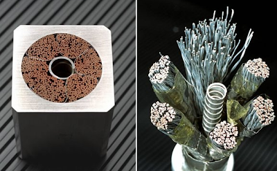


 is a small residual resistance in the superconducting windings due to
joints or a phenomenon called flux motion resistance. Nearly all
commercial superconducting magnets are equipped with persistent
switches.
is a small residual resistance in the superconducting windings due to
joints or a phenomenon called flux motion resistance. Nearly all
commercial superconducting magnets are equipped with persistent
switches.


 Superconductors inside magnetic rings will contain the plasma.Credit : Lockheed Martin

 Credit : Lockheed Martin and Google Solve for X
 Credit : Lockheed Martin and Google Solve for X
 Credit : Lockheed Martin and Google Solve for X


 - See more at:
http://www.rtcc.org/2015/09/09/renegade-uk-physicists-say-theyre-on-fast-track-to-nuclear-fusion/#sthash.7XRGljXp.dpuf
- See more at:
http://www.rtcc.org/2015/09/09/renegade-uk-physicists-say-theyre-on-fast-track-to-nuclear-fusion/#sthash.7XRGljXp.dpuf


No comments:
Post a Comment